Suitable motor driver for wheelchair using a 24V DC Motor Rated Current: 14 A controlled in arduino UNO

hello! can anyone suggest what motor driver will work for our project. it will be an automated wheelchair, but our problem is we don't know what motor driver we will use. In our previous trial, we tried to use the BTS7960, but after days of trials, the driver suddenly stopped working (i don't know if it's broken or not).

Provided below is the code that we used using the BTS7960

/* define BTS7960 motor drive control pins */
int LeftF = 12;
int LeftR = 13;
int RightF = 9;
int RightR = 10;

#define PWM 11

byte com = 0;

void setup() {
  
Serial.begin(9600);
Serial.println("START");

pinMode(RightF,OUTPUT);
pinMode(RightR,OUTPUT);
pinMode(LeftF,OUTPUT);
pinMode(LeftR,OUTPUT);

Serial.write(0xAA);

Serial.write(0x37);

//delay(1000);

Serial.write(0xAA);

Serial.write(0x21);
}

void loop() {

  while(Serial.available()) {

  com = Serial.read();

  switch(com) {

      case 0x11:   //command 1 is for move forward 

      //case forward:
      MotorForward();
      delay(6000);
      MotorStop();
      break;

      case 0x12:  //command 2 is for move reverse

      //case reverse:
      MotorReverse();
      delay(4000);
      MotorStop();
      break;

      case 0x13:  //command 3 is for turn right
      //case right:
      TurnRight();
      delay(1500);
      MotorStop();
      break;
    
      case 0x14:  //command 4 is for turn leftt
      
      //case left:
      TurnLeft();
      delay(1500);
      MotorStop();
      break;

      case 0x15:  //command 5 is for stop
      
      //case stopp:
      MotorStop();
      break;

            }
      }
}

/*FORWARD*/
void MotorForward()                                 //Clockwise
{
  digitalWrite (RightF, HIGH);
  digitalWrite (RightR, LOW);
  digitalWrite (LeftF, LOW);
  digitalWrite (LeftR, HIGH);
  analogWrite (PWM, 80);                       //0 - 255
  Serial.println ("MOTOR RUNS FORWARD");
}

/*REVERSE*/
void MotorReverse()                                //Counter-clockwise  
{
  digitalWrite (RightF, LOW);
  digitalWrite (RightR, HIGH);
  digitalWrite (LeftF, HIGH);
  digitalWrite (LeftR, LOW);
  analogWrite (PWM, 150);
  Serial.println ("MOTOR RUNS REVERSE");
}

/* TURN RIGHT */
void TurnRight() {
  digitalWrite(RightF, LOW);
  digitalWrite(RightR, HIGH);
  digitalWrite(LeftF, LOW);
  digitalWrite(LeftR, HIGH);
  analogWrite (PWM, 100);
  Serial.println ("MOTOR TURNS RIGHT");  
}

/* TURN LEFT */
void TurnLeft() {
  digitalWrite(RightF, HIGH);
  digitalWrite(RightR, LOW);
  digitalWrite(LeftF, HIGH);
  digitalWrite(LeftR, LOW);
  analogWrite (PWM, 100);
  Serial.println ("MOTOR TURNS LEFT");
}

/*STOP*/
void MotorStop()
{
  digitalWrite (RightF, LOW);
  digitalWrite (RightR, LOW);
  digitalWrite (LeftF, LOW);
  digitalWrite (LeftR, LOW);
  analogWrite (PWM, 0);                  
  Serial.println ("MOTOR STOPS");
}

(the project is controlled by voice recognition)

We are using 2 units of 24V DC Motor with a rated current of 14A to maneuver the back wheels of the wheelchair, and 2 batteries of 12V with 22Ah
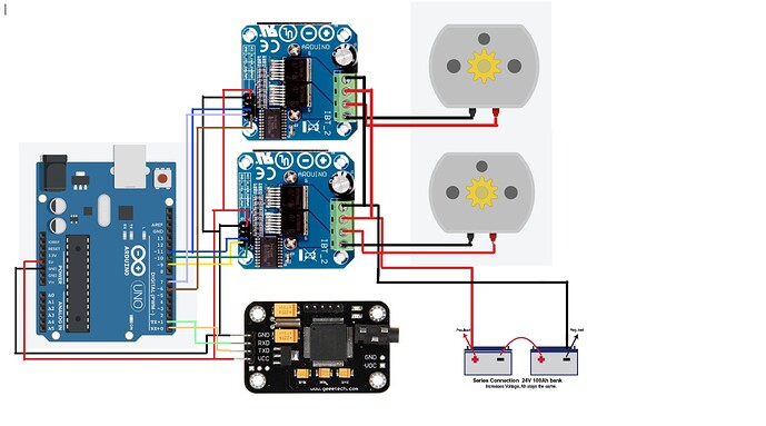
2 Likes

Both drivers or only one?

both drivers :<

Then your circuit is faulty, somehow. Can you draw a circuit diagram?

1 Like


this is the only diagram i have

Sorry, I cannot decipher what it means. Fritzing is not a valid replacement for a circuit diagram :frowning:

1 Like

i see :frowning: i'll try to create

The 14A is the current used while the motors are turning. Use your Ohmmeter to measure the resistance of one of the motors. While disconnected, of course. Use Ohm's law to compute the current that motor resistance will draw and that will be the current needed to start EACH motor to move. That total value is what your design must work with, NOT the running current of the motors.

The BTS7960 has impressive maximum currents listed, 60A for the low side and 80A for the high side driver.

Therefore it is possible to use the current limitation for a short time without exceeding the maximum allowed junction temperature.

So permanent overheating due to poor cooling may have killed the chips.

The start/stall current of brushed DC motors is 5 to 10 times higher than the rated running current.

Choose a motor driver that can handle well over 100 Amperes.

can you suggest a motor driver that will work for that DC motor?


can you check this :slightly_smiling_face:

It's still puzzling. You indicate 4 separate PWM wires and combined R/L_EN pins. Please remove the Arduino board image and write the pin names used in your code to the wires out of the driver chip.


like this?

Yes and no. I asked for the pin names used in code. There you have one pin named PWM that controls both motors at the same time. This won't work :frowning:

1 Like

hello! sorry for misunderstanding :sob: could you please check this diagram once again

Your diagram is clear now :slight_smile:

If you compare the pin names then you see that your Arduino PWM pin is not connected to the driver PWM pins.

could that be the reason why the motor driver doesn't work anymore?

Was the driver ever working as expected?

Perhaps it works if you rewrite your code and use the driver pins according to their names?

There is a major fault in the circuit. The motor ground is not connected to the logic ground. These are connected in the BTS7590 module. It is possible a fault or transient destroyed that connection. This can cause the BTS IC ground to lift possibly destroying it. That is the only weak spot I know about in the module and the data sheet warns you about it. It also has thermal shutdown which if used a lot can cause early failure. It also has a status output that you can monitor to determine what the fault really is, always much better than guessing.

1 Like