Supersizing my LED stairs project

Hello everyone,

Short version: electronics newbie. Skip unless you're bored
I work in IT and have been exposed to just about everything a firm can throw at you. I will be starting a series of training starting mid-September and running about 6 months that will take 100% focus. To prep for this, I need to disengage my mind and do something new. I have zero experience with arduinos, electricity, soldering, robotics... and just about everything else hobby/maker related. As of last week, I have given myself 4 weeks to jump in, close the knowledge gap, and make something cool!

Project Overview
I have 13, ~4' wide steps to get to the top of my stairs. I would like to put 2' strips of LEDs (8m/240 LEDs) down the center of the steps. The top and bottom of the stairway would each have a PIR sensor, and it would be run by an Arduino. I know this project has been done a dozen times, and I've waited to post until I had made some progress on my own. It seems like the guides assume a level of prior knowledge, so I need a little help.

Adafruit NeoPixel 30 LED/m

Prototype
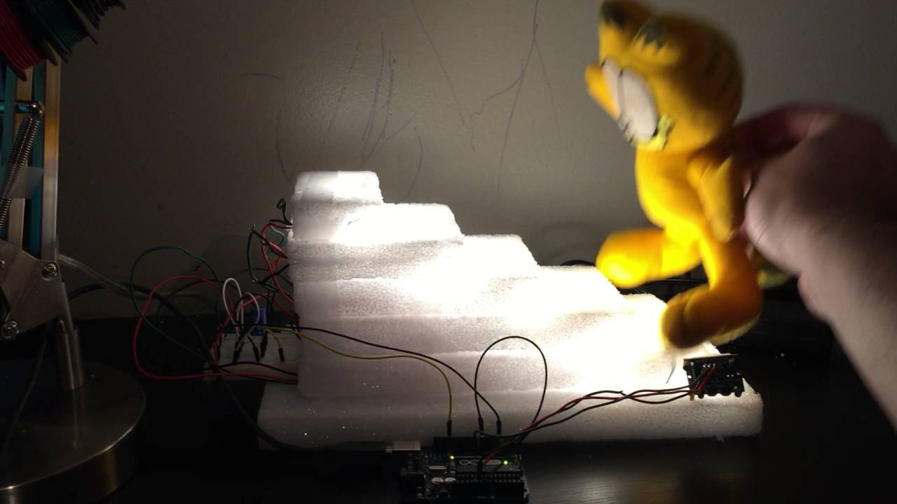
I'm too much of a perfectionist to go for the real deal, so I started small. I went on a little shopping spree and go myself some materials to make a prototype: Arduino Uno, Soldering Kit, wires, breadboard, etc.

I cut up some foam to look like steps, connected the wires according to guides from the net, added the resistor and capacitor as the adafruit lesson recommended and cut/pasted/hacked some code together to do what I wanted (fade up when bottom sensor is tripped, and down when top sensor is tripped). (see attachment).

Challenges / Next Steps
I have about 2 days of electrical knowledge from building this prototype (I didn't really know the difference between AC and DC before this). I'm here to make sure I'm doing things as safely as possible. According to my research, the RGBW LEDs linked above can consume up to 80mA at full blast. 240 LEDs x 80mA = 19.2A.

I have an ATX power supply that outputs DC 5v at 25A max on one pin, and DC12v at 62A max on another.

Considering that the 5v rail is said to be unstable without load on the 12v, Would it be a good idea to power the Arduino from the 12v and the LEDs from the 5v? Or should I use something like this Singpad 5v 30A Power Supply

If I do go with the Singpad power supply, how would I power the Arduino (9v-12v) from it? or would I need a separate power supply?

Some charts are suggesting 4-8 guage wire. Will I be able to solder that size onto the LEDs?

Does the resistor and capacitor size need to change?

Are there additional parts that I should consider when scaling this up? For example, I read about an in-line fuse holder that sounded like it was a good idea.

These may be silly questions, but again I'm very new to this stuff.

Thanks,
Morv
Considering that the 5v rail is said to be unstable without load on the 12v, Would it be a good idea to power the Arduino from the 12v and the LEDs from the 5v?

I don't see where the link discusses this issue FOR YOUR SPECIFIC POWER SUPPLY. I don't see anywhere where they mention what constitutes a suitable load on the 12V side. I doubt, though, that the Arduino would provide sufficient load.

Or should I use something like this Singpad 5v 30A Power Supply

Why not get one of the power supplies that Adafruit recommends/sells?

If I do go with the Singpad power supply, how would I power the Arduino (9v-12v) from it? or would I need a separate power supply?

A $2 wall wart is not going to be a deal breaker, is it?

Some charts are suggesting 4-8 guage wire. Will I be able to solder that size onto the LEDs?

Have you seen an 8 gauge wire? A 6 gauge wire? A 4 gauge wire?

My hot tub uses 8 gauge wire, through a 50A, 240VAC breaker. I seriously doubt that you need as heavy, or heavier, wire for some LEDs.

Does the resistor and capacitor size need to change?

No. The values stay the same, but you need to make sure that the ones you get can handle the current.

How are the LEDs wired, in series or in parallel? In parallel a low voltage and high current supply is needed, for series high voltage and lower current.

PaulS:
I doubt, though, that the Arduino would provide sufficient load.

The arduino would be sending out the signals to the LED, do you mean that it wouldn't go through to the 144th LED (going through about 40ft of wiring, 26ft of LED strip)? Is there a solution for that?

PaulS:
Why not get one of the power supplies that Adafruit recommends/sells?

Adafruit sells 5v power supplies with 10A max. I'll need at least 2 of them to power the LEDs. I read that the less components the safer and more stable it would be.

PaulS:
A $2 wall wart is not going to be a deal breaker, is it?

You mean instead of this obviously over-my-head project? Where's the fun in that?

PaulS:
Have you seen an 8 gauge wire? A 6 gauge wire? A 4 gauge wire?

My hot tub uses 8 gauge wire, through a 50A, 240VAC breaker. I seriously doubt that you need as heavy, or heavier, wire for some LEDs.

Although I have found that 12 gauge is minimum for 20A, according to wire gauge charts on google, 20A through 40ft of wire should be be on 4 gauge.

DrDiettrich:
How are the LEDs wired, in series or in parallel? In parallel a low voltage and high current supply is needed, for series high voltage and lower current.

I was thinking in series just because that's what made sense in my mind. But I guess if the data-in and data-out stays the same, I could power it either way.

For Parallel I need 5v 1.44A to power each of the 13 steps (18 LEDs)
For Series I need 5v 19.5a to power 144 LEDs

Other than requiring 50% less wiring in parallel (data would still require the same amount), are there any other benefits or changes that I would need to consider?

If a strip is powered by 5V, the LEDs on it are mounted in parallel. This means that the strips have to be powered in parallel, too, with common Gnd and Vcc (5V). You only have a choice of programming the strips in parallel or in series. Details depend on the type of the strips - do you have a datasheet?

I realized that there is an outlet available from beneath the stairs. To keep it simple, I'm going to use 2 of the 5v 10A to power the LEDs and 1 of the 9v 1A to power the Arduino, all connected to a power strip.

Also did some research on parallel circuits (thanks DrDiettrich). I don't know why I would want to power it in series.

Looking at other projects with similar size stairs, they're using 18 awg. Does that sound about right, or should I go thinner?

Also, any idea on how long the data wire can be from the arduino to the last LED?

DrDiettrich:
If a strip is powered by 5V, the LEDs on it are mounted in parallel. This means that the strips have to be powered in parallel, too, with common Gnd and Vcc (5V). You only have a choice of programming the strips in parallel or in series. Details depend on the type of the strips - do you have a datasheet?

Yes, I have the WS2812B datasheet

DrDiettrich:
If a strip is powered by 5V, the LEDs on it are mounted in parallel. This means that the strips have to be powered in parallel, too, with common Gnd and Vcc (5V). You only have a choice of programming the strips in parallel or in series. Details depend on the type of the strips - do you have a datasheet?

The OP mentions using NEOPIXELS in the first post.

Thanks for the feedback everyone, Here is what I decided to go with:

8 meters of Neopixel RGBW 60LED/m
18 AWG hook-up wire
5v 60A switching power supply

I'll be wiring it in parallel and sticking them to the steps with liquid nail with LEDs pointing down.

I got some in-line fuse holders with 40A fuses. Are there any other safety precautions I can take to make sure the system runs smoothly?