If you would be so kind - I want to switch a Thermoelectric Peltier Cooler (TEC1-12705) (12V - 77 Watts) using an Uno. I am an engineer but not an EE so I could use some guidance on what is simplest and cheapest device to achieve simple on off control based on temperature feedback. I would appreciate any help on what device to use: relay, SSR, MOSFET, BJT etc...
That 77W is not a fixed number with those TECs.
I think the TEC1-12705 (2 or 3 dollars on Ebay) is 5A at 12V.
Let's say it can vary 30%, so you need to be able to switch at least 6.5A, and for safety let's say 10A.
Two options: relay or mosfet.
With a relay is safer, because the Arduino is not connected to the power of the TECs and ground current can not destroy the Arduino.
With a mosfet is more fun and make no noise when switching.
Thank you for the advice, I found those MOSFETs just a few minutes ago and ordered a couple. I think the MSOFET, despite the risks, will be a cheaper solution. Can you provide any advice on circuit protection when using the MOSFET just in case?
You protect the Arduino and the mosfet with a resistor of 150 ohm or 1k or so from the Arduino output to the gate of the mosfet.
An optocoupler can protect the Arduino for ground currents. That might be a good idea now that I think of it.
Something like the schematic here : 12v Dimmer Circuit incl. schematic, few questions - #3 by system - Interfacing - Arduino Forum
Although I prefer the 10k to ground and the optocoupler output to the 12V and gate.
I would grab one of these with a temperature sensor.
The DHT11 and DHT22 modules give temperature and relative humidity.
The DS18B20 one wire units are cheap temperature only sensors. (nice waterproof versions too)
This stuff is just a couple of bucks, assembled, ready to be wired.
Thank you all for all the advice. I will let you know how it all works out. I am going to try both a opto/mosfet combo and the relay circuits to see how they compare!
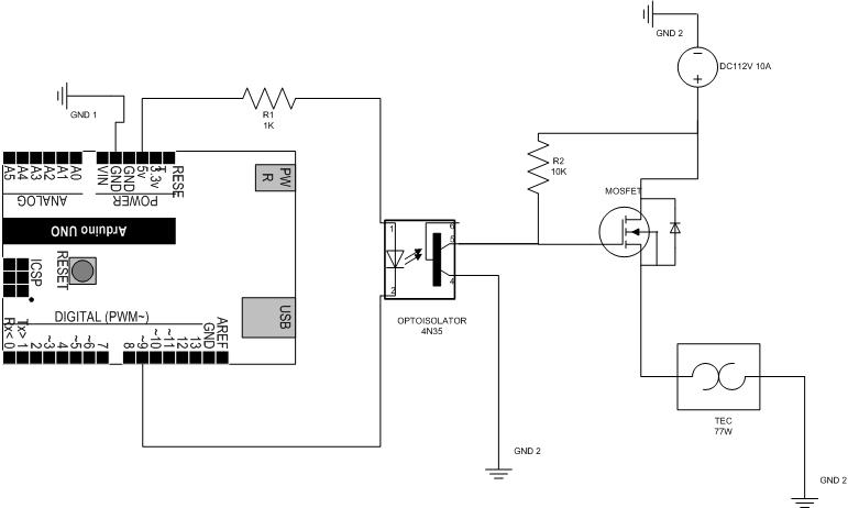
Here is my circuit - all assistance is welcome because I am not sure at all about this working!
My gut says that pin9 should be the feed to the opto with the other opto pin to gnd. By setting 9 to high it turns on the diode and triggers the opto output to the mosfet but that is not how it was wired for the dimmer. I am not looking to use PWM just simple on off control for the thermal electric cooler (TEC).
The MOSFET I plan to use is an N Channel rated at 60V and 30 amps - not sure if that is what I have drawn!
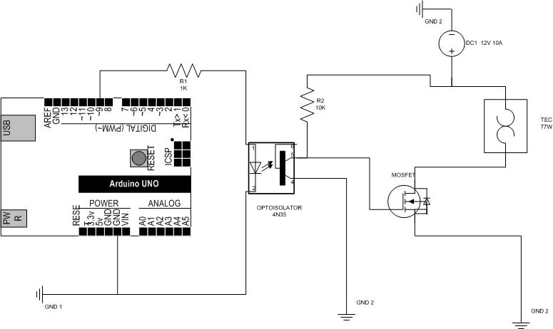
That's the wrong configuration for switching - you must have load between supply and drain, source
terminal to 0V / ground.
Remember the gate has to be 5V above the source voltage to turn the device on, so the
source must be at 0V. (All assuming n-channel logic-level FET).
PS You probably want the opto coupler pulling the gate high, not down to
ground, so that the MOSFET is off when the Arduino is powered down...
Given your load circuit is all 12V you don't need logic-level MOSFET, For 10A a
beefy device is needed, perhaps 5 milliohm or lower, if you want to avoid a large
heatsink
I am not all that familiar with this type of circuit design and I have seen several examples and dot fully understand the difference. Just to be clear I am trying to switch a 12V 10 amp device.
This circuit listed under another topic is supposed to work
sorry ... but I guess your schematic is still not perfect. First of all: you use a pullup on the gate of the mosfet. As a result of this your Motor will be switch on even if you don't have a connection to the Arduino. Only if the Arduino pin is HIGH then your motor will be switched off. I'm not sure if this is the behaviour you want to achive!
Beside of this you should also add a 100 Ohm resistor to the gate if you do not plan to run the mosfet with PWM. This will reduce EMC. Another 100k resistor between gate and GND will alow the mosfet to uncharge it's gate capacity and gives a defined low for the mosfet.
And last but not least: you should try to get familliar with some "normal" CAD for schematics like KiCad. Your schematic is a little bit hard to read to be honest
Here an untested example like I would try to go forward:
That particular unit is made in China by BC Relay, AKA Shaanxi Qunli Electric Co., Lt. BC stands for 'Best China'. They are also made by Yueqing Hengwei Electronics, Zhejiang Zhonji Technology, Zhejiang Asia Dragon Relay, and other Chinese manufacturers. if they carry the JQX designation, they all meet the same Chinese government controlled specifications.
I purchased 10 of these exact BC Relays from an eBay vendor last year for $9 including shipping. None have melted. Just saying. But if you want to give the extra $ to SparkFun, hey, whatever.
The gate of a MOSFET is isolated. I do not see why you would need an opto-isolator if proper grounding was unitized. Even still, an opto-isolator is easy to use and this would be a good opportunity to learn how to use one.

