I wanted to drive steper motor NEMA 17 in both direction by a three-state-switch, Motor is working fine by changing HIGH, LOW on direction pin of A4988. but I wanted to give an input 5V in analog pin 2 and 3
Where :
analog 2 having 5V and analog3 is 0V, direction pin will be HIGH, motor clockwise
analog 3 having 5V and analog2 is 0V, direction pin will be LOW, motor anticlockwise
For 3 state switch i connected common terminal on arduino 5V, and other two terminals in A2 and A3.
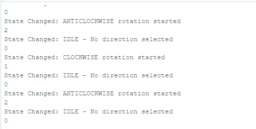
When i provide power, motor start vibrating and sometimes it rotate a bit in clockwise, sometimes automatically start rotating anticlockwise. It happens when switch is in OFF mode as well.
PLEASE HELP me to find out whats wrong.
I was trying to use this code:
const int stepPin = 2;
const int dirPin = 4;

// Define analog input pins for mode selection
int analogPin2 = A2;     // Clockwise selection
int analogPin3 = A3;  // Anticlockwise selection
int cw = 0;
int acw = 0;


void setup() {
  // Setup the output pins for the stepper motor
  pinMode(stepPin, OUTPUT);
  pinMode(dirPin, OUTPUT);


}

void loop() {
  // Read the current state of the mode pins

  if(analogRead(analogPin2)>3){
  cw = 1;


  }
  else if (analogRead(analogPin3)>3){
  acw = 1;

  }


  if(cw == 1){
    digitalWrite(dirPin, HIGH); // Set direction for clockwise
    // Generate 200 step pulses
    for (int x = 0; x < 200; x++){
      digitalWrite(stepPin, HIGH);
      delayMicroseconds(600);
      digitalWrite(stepPin, LOW);
      delayMicroseconds(600);
    }
    delay(1000); // Pause after completing the rotation
  }

  else if (acw == 1){
    digitalWrite(dirPin, LOW); // Set direction for anticlockwise
    // Generate 200 step pulses
    for (int x = 0; x < 200; x++){
      digitalWrite(stepPin, HIGH);
      delayMicroseconds(600);
      digitalWrite(stepPin, LOW);
      delayMicroseconds(600);
    }
    delay(1000); // Pause after completing the rotation
  }
  // Otherwise, leave the motor off (no pulses issued)
  else {
    // Optionally, you can set the step pin LOW to ensure the motor is not being driven
    digitalWrite(stepPin, LOW);
    // Short delay before checking the inputs again
    delay(500);
  }
}
Try swapping over one of the coil windings going to the motor. Also try running it much slower.
That is wrong and the the center position will leave the other two pins floating, that is not being connected to anything. Why are you using analogue pins anyway?
To stop the pins floating you need to use pull up resistors on your input pins, or enable the internal pull up resistors. I see no evidence of doing this in your code.
I think coil sequence should be alright, cause i check without switching, by changing Direction pin HIGH/LOW in this code:
//#define DIR_PIN 4
//#define STEP_PIN 2

const int stepPin = 2;
const int dirPin = 4;


void setup() {
  // Sets the two pins as Outputs
  pinMode(stepPin,OUTPUT);
  pinMode(dirPin,OUTPUT);

}
void loop() {
  digitalWrite(dirPin,LOW); // Enables the motor to move in a particular direction
  // Makes 200 pulses for making one full cycle rotation
  for(int x = 0; x < 200; x*1) {
    digitalWrite(stepPin,HIGH);
    delayMicroseconds(600);
    digitalWrite(stepPin,LOW);
    delayMicroseconds(600);


  }
  delay(1000);
}
It worked.
Then I just modified this code by adding the conditions. the code was written by me. I chose analog pin cause I was giving 5V to read for Arduino UNO R3.
It worked means, the motor was rotating both direction then Direction pin mode was changed in code.
I tried with digital pin . with that code, still having same issue.
const int stepPin = 2;
const int dirPin = 4;

// Define input pins for mode selection
const int cwPin = 12;      // Clockwise selection: When HIGH and antiCW is LOW
const int antiCwPin = 13;  // Anticlockwise selection: When HIGH and cwPin is LOW

void setup() {
  // Setup the output pins
  pinMode(stepPin, OUTPUT);
  pinMode(dirPin, OUTPUT);

  // Setup the mode input pins
  pinMode(cwPin, INPUT);
  pinMode(antiCwPin, INPUT);
}

void loop() {
  // Read the current state of the mode pins
  bool cwState = digitalRead(cwPin);
  bool antiCwState = digitalRead(antiCwPin);


  if(cwState == HIGH && antiCwState == LOW){
    digitalWrite(dirPin, HIGH); // Set direction for clockwise

    for (int x = 0; x < 200; x++){
      digitalWrite(stepPin, HIGH);
      delayMicroseconds(600);
      digitalWrite(stepPin, LOW);
      delayMicroseconds(600);
    }
    delay(1000);
  }

  else if (antiCwState == HIGH && cwState == LOW){
    digitalWrite(dirPin, LOW); // Set direction for anticlockwise

    for (int x = 0; x < 200; x++){
      digitalWrite(stepPin, HIGH);
      delayMicroseconds(600);
      digitalWrite(stepPin, LOW);
      delayMicroseconds(600);
    }
    delay(1000);
  }

  else {

    digitalWrite(stepPin, LOW);

    delay(500);
  }
}
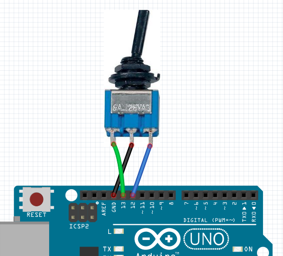
This is the circuit i was using, , and the switch is in circle.....one in attached with 5V pin of arduino...and other two in D12 and D13. arduino is powered from PC by usb, it was having 5V input.
A switch needs pull up or pull down (resistors).
In your current diagram, D12 and D13 are "floating, and can change between High and Low at will. Either use two 10k resistors from each pin to ground, or..
wire the middle pin of the switch to ground (not 5volt), and use INPUT_PULLUP.
Leo..
I would use the wiring in in post #10, then make input D12 & D13 to be of the INPUT_PULLUP type in your setup function.
This way you are switching the ground, a much better idea than switching the 5V.
Then you will have to change your code to take this into account. That is you will get
Switch to left - D12 = 0, D13 = 1
Switch to center - D12 = 1, D13 = 1
Switch to right - D12 = 1, D13 = 0