Hello,
I am building an IR Sensor Switch with a TCRT5000 sensor.
I am using a sketch found on instructables.com, which removes the ambient noise from the reading
and works like that:
a = meassure IR light when IR LED is on: noise + signal
b = meassure IR Light when IR Led is off: noise
c = (noise + signal) - noise = signal
My Code:
const int tcrtDetectorPin = A0;
const int tcrtEmitterPin = D8;

int a, b, c;

void setup() {
  Serial.begin(115200);

  pinMode(tcrtDetectorPin, INPUT);
  pinMode(tcrtEmitterPin, OUTPUT);
}

void loop() {

  digitalWrite(tcrtEmitterPin, HIGH);
  delay(1);
  a = analogRead(tcrtDetectorPin);
  digitalWrite(tcrtEmitterPin, LOW);

  delay(1);
  b = analogRead(tcrtDetectorPin);

  c = a - b;

  Serial.print(a);         //noise+signal
  Serial.print("\t");
  Serial.print(b);         //noise
  Serial.print("\t");
  Serial.println(c);       //denoised signal
  delay(20);

}
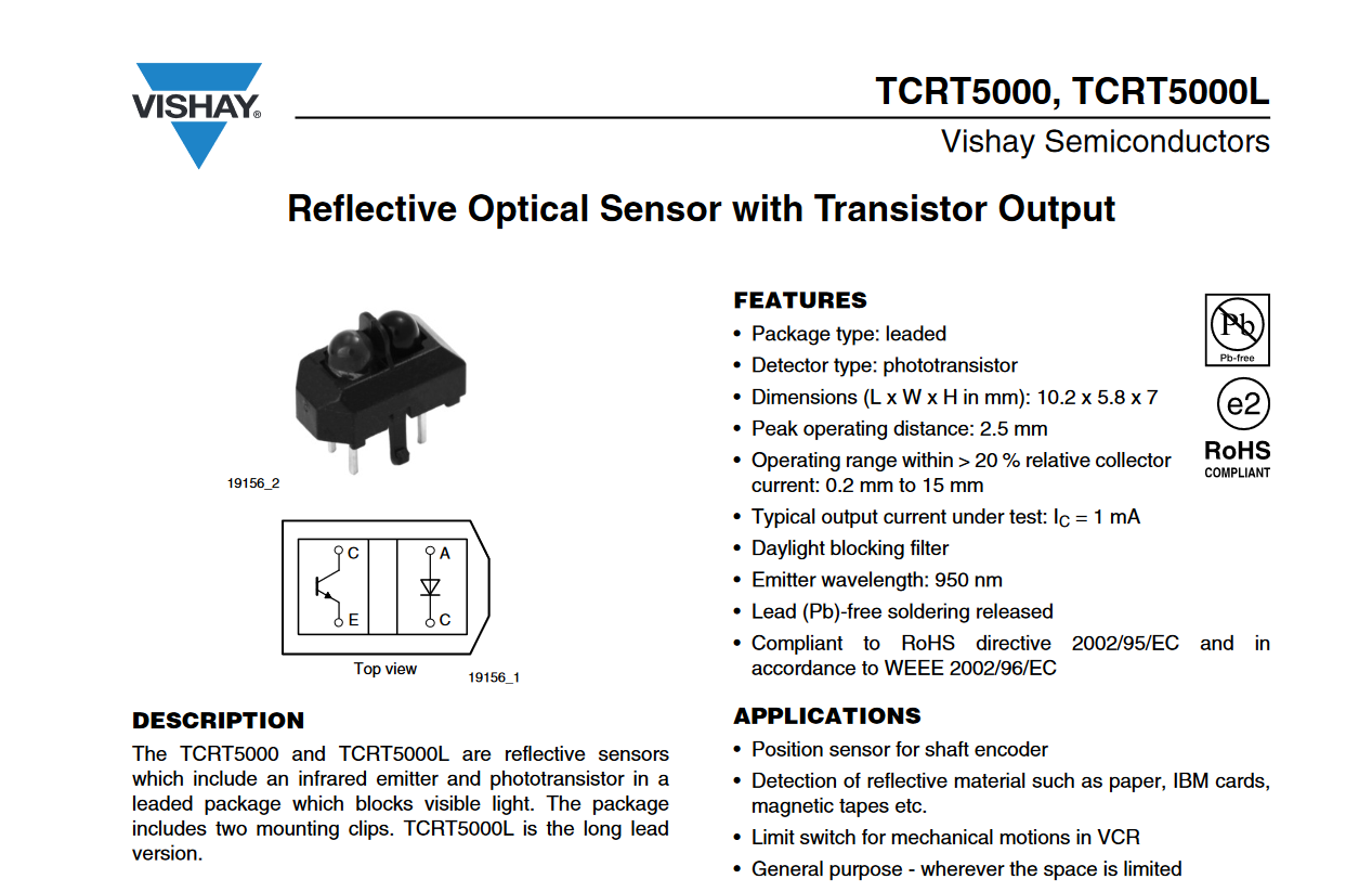
My TCRT5000 is connected as shown in the attachment.
I am testing it in a bright room.
I observe the values of a, b and c on the Serial Ploter of the IDE, see picture plot.png.
Left and Right: NO Hand infront of Senosr
Middle: Hand infront of Sensor
-
Why is it that the "noise" is higher than the "noise + signal" when nothing is infront of the sensor? Shouldn't it be the other way around, because the sketch takes care of that?
-
When I shine a light on the sensor the "noise" value gets higher but the "noise + signal" stays at the same value, Why?
-
The TCRT5000 datasheet mentions a "Daylight blocking filter", what does it block? Is that the reason the "noise + signal" value stays the same even when a bright light is shined on the sensor?
Thank you