Here is the latest schematic for my TDR (because I have just been asked for it). I still need to add a voltage regulator so that I can run it from a battery, and an LCD to display the result. The software needs to be updated because I am now using 2 pins to produce the voltage step to drive the cable, so that I can use a lower value resistor (75 ohms). This will be a better match to most cables than the 150 ohms that I was using previously.

Glad to see your progressing with the project. Once again I am waiting for parts/information, this time a solder mask for the QFN32 chip from a company in Canada though I'm tempted to order one of these as I could have it here next day and no need of a mask.
I found an application note for the GP22 for using it in a laser range finder so hopefully I'm on the right track here (instead of using 2GHz clocks).
Hi, I'm doing a final year electronics project and have chosen to build a TDR for finding faults in a electric cattle fence.the resolution does not need to be that small because faults can be physically seen. the aim of the project is to speed up the process of troubleshooting an electric fence. i am considering whether I will use mBed or Arduino.
I am told that the arduino uno/leonardo, etc. gives trouble when connecting through the laptop through the serial port and also posed other problems while programming when a shield was attached. Therefore i want to avoid using these. The arduino Mega was ok though.
The mBed LPC1768 has a faster clock speed (96MHz) than the mega which should mean that it should give a better resolution. However i have read that the pulse-width is limited to 10us nut this is while the clock is at a default speed of 12MHz so hopefully i can get a fast rise-time out of it if i increase the clock speed.
I am conscious though that i cannot find any sample code for a tdr for mbed and converting code for an arduino to suit mbed may be problematic. so i may be better off using an arduino and using external electronics to speed it up.
Any advice would be greatly appreciated.
Hi,
I'm not sure what you mean by "the arduino uno/leonardo, etc. gives trouble when connecting through the laptop through the serial port and also posed other problems while programming when a shield was attached". Lots of people are using these Arduinos. If you use a Leonardo then you don't program via the Arduino serial port, you program directly through the USB port.
What resolution do you require? You will find several different approaches described earlier in this thread, including:
-
My very simple TDR using an Arduino and a high-speed comparator. Resolution is limited to 62.5ns (about 15 to 30 feet depending on cable type) using a standard 16MHz Arduino, although by migrating the design to a 20MHz standalone atmega328p, you could improve this to 50ns (about 12.5 to 25 feet).
-
A modification to my TDR design which adds a variable delay line, improving the resolution to 1ns or better.
-
Riva's idea for a TDR using the GP22 chip. This is a very nice looking chip and should provide very high resolution.
Well when we were learning code with the leonardo last year we kept on having to plug the usb in and out and change the serial port say from com3 to com11 and even when you got the program to upload, it might not work the next time. as far as i know last years class also had problems with the uno and possibly the duememilanova that delayed their progress but they werent as bad as the leonardo. so the lecturer said to use the mega because they were able to get that going easier last year. the lecturer also recommends the mbed because they are much easier to use.
Practically a resolution of 15 feet would be adequate because if you just had the general area of the fault, you could visually inspect the wire in that area and if there is a post in the area then you can tell that the post is the cause of the fault.
I was also thinking about being able to change the pulse width of the transmitted signal.So the smallest pulse width would be used first to scan the immediate area then you would toggle up through increasing pulse widths to scan further out the fence line. i have read that increasing the pulse width can make the position of faults clearer because the energy of the signal is dissipated as it travels through faults.
t00158713:
I was also thinking about being able to change the pulse width of the transmitted signal.So the smallest pulse width would be used first to scan the immediate area then you would toggle up through increasing pulse widths to scan further out the fence line. i have read that increasing the pulse width can make the position of faults clearer because the energy of the signal is dissipated as it travels through faults.
My TDR design uses a step function, not a pulse. The advantage is that there is only one edge to be reflected and detected. If you use a pulse, then you need to try to work out whether each of the received steps are reflections of the leading or the trailing edge of the pulse.
Yes, that sounds like it would make things simpler. Does your design just send out a single rising edge?
If so I would imagine that the range would be large enough. Any idea what is the maximum length of cable you can test?
An elerctric fenceline would be several kilometres long. I would not need to test the entire fence as i could travel out farther with the faultfinder. However there are a lot of joinings which would dissipate the signal so a large range is desirable for my TDR.
t00158713:
Yes, that sounds like it would make things simpler. Does your design just send out a single rising edge?
It sends out a series of pulses, however the trailing edge of the pulse doesn't occur until after the reflection has been detected. Between pulses, it adjusts the threshold on the comparator, so that it can search for the reflection. You can find the details earlier in this thread, in message TDR (Time-domain reflectometer) concept. On the right track? - #10 by dc42 - General Electronics - Arduino Forum. In my revised design at TDR (Time-domain reflectometer) concept. On the right track? - #21 by dc42 - General Electronics - Arduino Forum I've added some protection for the microcontroller and the comparator. I also added the delay line, but you won't need that because you don't need higher resolution than the basic version provides. Note that the software needs modifying for that version, because it uses 2 output pins in parallel to drive the cable.
PS - I suggest you start by determining the impedance of your electric fence and the speed of signal transmission in it. To measure the impedance, generate a pulse from an Arduino, feed it into the fence through a resistor, and look at the size of the initial step on an oscilloscope. To determine the speed, short the fence to ground a known distance away (at least 100') and measure the time to the reflected pulse on the oscilloscope. See cable fault locator help - #9 by dc42 - Project Guidance - Arduino Forum for what you should see (the last 2 pictures were taken using a step).
I presume the electric fence is single-wire. What are you going to use as the ground connection? Are there other non-electric wires in the fence that you can rely on to be continuous, or will you have to use an earth spike?
When you say joinings, what do you mean? Just another length of wire, or multiple wires joining to one point?
Thanks for the advice. I will have to use a ground spike(the fence is single wire and is earthed near the energiser/fencer with a long probe going into the ground).
The joinings in the fenceline include 'junctions' where the path splits in two. If there is a fault in one or both of the paths after a junction then the TDR would not be able to tell which path the fault(s) come from. Therefore you would have to test each path individually to find out where the fault is.
I wonder if it would be possible to map out all distances between the junctions on the fenceline and then pinpoint the location of the fault on the map using the following method.
Say you would expect a junction on 'path 1' 50 metres after the first junction and junction on 'path 2' 30 metres after the first junction.
Then if the TDR reads a fault 20 metres out from the first junction and then a junction 50 metres out from the first junction then you know the fault is on 'path 2'. Then you coud display on an LCD the map of the fence with 'path 2' flashing in red to show there is a fault there. The TDR would probably have to be fixed near the energiser for this unless you could tell it where on the map you are.
The main problem with this idea however is that after a few junctions the signal might be dissipated. I will first build the TDR and see if it would be possible after that.
You will also get a reflection from every junction, which will make it difficult to locate a fault after a junction.
What sort of faults are you looking for: open circuit wire, short circuit to ground, or both? A junction will look like a short circuit (i.e. the reflected pulse is inverted), but with lower amplitude than a dead short. So detecting an open circuit after a junction may be easier than detecting a short circuit after a junction.
I will be looking for both opens and shorts but a short circuit is the most likely.
From what gathered from research TDR manuals, the reflections at connections are a negative reflection followed by a positive reflection. This would mean that not much of the signal is lost (because the two reflections would cancel each other out).
If I
I will be looking for both opens and shorts, but a short circuit is the most likely in the event of a fault.
From what I gather from TDR manuals, the reflections at connectors are a negative reflection followed by a positive reflection. This would mean that not much of the signal is lost(because the two reflections cancel each other out).
If I'm going to be able to distinguish between junctions and faults, I expect I'll need a higher resolution and possibly to change the code a bit (to be able to see the two reflections instead of just one). Would your TDR be able to do this?
t00158713:
From what I gather from TDR manuals, the reflections at connectors are a negative reflection followed by a positive reflection.
At a junction of 3 wires, I would expect you to see just a negative reflection. At the end of the wire (i.e. open circuit), you will get a positive reflection.
t00158713:
This would mean that not much of the signal is lost(because the two reflections cancel each other out).
You are bound to get a significant signal loss, because the energy you sent down the wire is being split. I think the manual refers to a very short discontinuity in impedance cause by a connector.
t00158713:
If I'm going to be able to distinguish between junctions and faults, I expect I'll need a higher resolution and possibly to change the code a bit (to be able to see the two reflections instead of just one). Would your TDR be able to do this?
The software can already see multiple positive reflections, or multiple negative reflections, or multiple positive reflections followed by multiple negative reflections. To see other combinations of multiple reflections, you would need to change the software to ignore the earlier reflections. This would only be possible if the reflections are well-separated in time. Alternatively, you could use external gating to hold off the comparator output for a while.
How much of a signal loss would you expect? If the tdr is going to tell me I have a short at every junction and then nothing after that, I may have to abandon the idea.
After looking at http://s2629002012.files.wordpress.com/2012/11/huitransmissionlines.pdf, I believe that at a junction of 3 wires, you will get 2/3 of the signal voltage propagating along the two branches, and 1/3 reflected back. If one of those branches contains a fault (i.e. completely open or short circuit), then 2/3 of the reflected signal would pass back through the junction. So you should see a negative reflection of 1/3 the initial amplitude (from the junction), followed by a positive or negative reflection of 4/9 the initial amplitude from the fault. Of course, this ignores the losses in the line itself.
Just a small update on this project. After much waiting/problems getting solder mask stencil to solder the GP22 chip (first one disappeared in the post but managed to get another sent after a lengthy delay) I finally got it soldered down about a week ago and have been writing test code and doing hardware debugging ever since.
Problem was the Arduino was talking to the chip fine over SPI but after initial time reading it continually timed out according to the status register. I found the cause was a problem with the oscillator circuit so after a bit more soldering I am now getting ever changing reading as I expect.
Starting...
Setup Interrupt. Current Pin State = 1
Starting SPI MODE1...
Taking Chip Out Of RESET
Configure GP22 Measure Mode 2
End Of Setup
delayMicroseconds = 1
Interrupt = 1
RES_0 = 26418	Difference from last reading = 26418
RES_1 = 466000
RES_2 = C00E4020
RES_3 = 26418
STAT = 10001
PW1ST = 0
delayMicroseconds = 2
Interrupt = 2
RES_0 = 5E54E	Difference from last reading = 38136
RES_1 = 26418
RES_2 = C00E4020
RES_3 = 5E54E
STAT = 10001
PW1ST = 0
delayMicroseconds = 3
Interrupt = 4
RES_0 = 7E626	Difference from last reading = 200D8
RES_1 = 5E54E
RES_2 = C00E4020
RES_3 = 7E626
STAT = 10001
PW1ST = 0
delayMicroseconds = 4
Interrupt = 6
RES_0 = 9E716	Difference from last reading = 200F0
RES_1 = 7E626
RES_2 = C00E4020
RES_3 = 9E716
STAT = 10001
PW1ST = 0
delayMicroseconds = 5
Interrupt = 8
RES_0 = BE7CA	Difference from last reading = 200B4
RES_1 = 9E716
RES_2 = C00E4020
RES_3 = BE7CA
STAT = 10001
PW1ST = 0
delayMicroseconds = 6
Interrupt = 10
RES_0 = DE8C6	Difference from last reading = 200FC
RES_1 = BE7CA
RES_2 = C00E4020
RES_3 = DE8C6
STAT = 10001
PW1ST = 0
delayMicroseconds = 7
Interrupt = 12
RES_0 = FE992	Difference from last reading = 200CC
RES_1 = DE8C6
RES_2 = C00E4020
RES_3 = FE992
STAT = 10001
PW1ST = 0
delayMicroseconds = 8
Interrupt = 14
RES_0 = 11EA46	Difference from last reading = 200B4
RES_1 = FE992
RES_2 = C00E4020
RES_3 = 11EA46
STAT = 10001
PW1ST = 0
delayMicroseconds = 9
Interrupt = 16
RES_0 = 13EB44	Difference from last reading = 200FE
RES_1 = 11EA46
RES_2 = C00E4020
RES_3 = 13EB44
STAT = 10001
PW1ST = 0
delayMicroseconds = 10
Interrupt = 18
RES_0 = 15EC1C	Difference from last reading = 200D8
RES_1 = 13EB44
RES_2 = C00E4020
RES_3 = 15EC1C
STAT = 10001
PW1ST = 0
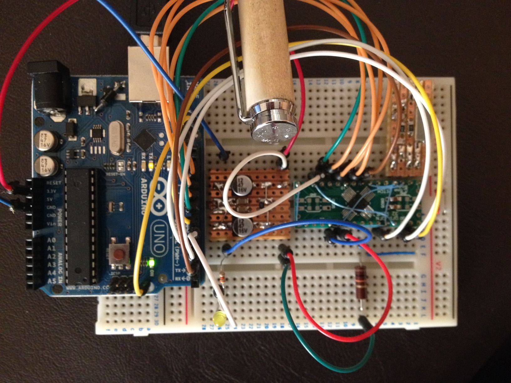
I'm glad to see that you are making progress. I haven't done any work on my design for a while, due to getting distracted by other projects. My 40-year old homebuilt bench supply developed a short after a bakelite capacitor support broke, taking several components out; so I've been designing a digitally-controlled voltage regulator to replace the existing one.
Yes, getting distracted by other projects is a problem. What with the 6 week delay in getting the solder stencil. A new engineer at work needed bringing up to speed (I try to do my soldering at work when I'm not busy) and teaching soldering/re-work skills I have not had much time. At least I finished the Arduino DMX tester for work. My problem now is finding the rest of the components for this project as they were built and tested weeks ago and now I cannot find them. Hopefully they will be in one of my toolboxes at work.
Hope you get your PSU up and running again.