Hello,
I'd like to program an Arduino Pro Mini without soldering permanent header pins on it. Is there a good way of doing this?
I've seen those clips used for multimeters to clip onto wires, but they're too big to clip several in a row for the Pro Mini. Thought maybe others might have some ideas.
Just stick the header through the holes and just keep a little pressure on them while programming
That's how I do it (although on a long edge) to burn a different bootloader (in bulk) the moment I get new Pro Mini's, before putting them away in my bin.
I'd like to program an Arduino Pro Mini without soldering permanent header pins on it. Is there a good way of doing this?
In my opinion this is one of the best ways of damaging your electronics. If the ground or positive becomes disconnected then the rest of the circuit just looks like a diode's drop.
Why not solder pins on it and then when you want to use it in a permanent application then you simply use a socket in your final device.
I've done that, you need to maintain good pressure on the header pins against the holes while the IDE does it's thing. I angle the pins sideways so they are making contact at the top & bottom of the Promini.
Lot easier to solder in pins, vertical or right angle, and just plug on your FTDI Basic or equivalent.
You can find right angle male & female headers that sit very low on the board, like I used here
starsson:
Hello,
I'd like to program an Arduino Pro Mini without soldering permanent header pins on it. Is there a good way of doing this?
Maybe. Could possibly get some over-sized vias (or BNC pins), and solder each via (or BNC pin) to the end of a WIRE of the programming cable. Then lightly jam each over-size via (or BNC pin) into the arduino board holes. Pins of a suitable size should provide a snug fit. But obviously, don't jam too tightly. Jam firmly, but don't force it.
Once you're finished programming.... just lightly pull the pins back out again. The concept is.... using a pin of just the right size...... to allow for a relatively snug fit in the hole. But yet can pull the pin out again.
INTP:
If you know how to solder, then it shouldn't be a problem soldering and desoldering headers.
What is your aversion to headers?
I have two wires soldered in for I/O. It would be nice to just clip in the programming, program, and then clip off, rather than have to breakout the soldering iron to make a change. If I need to make adjustment - clip in, program, clip out. I don't have the soldering iron out all the time, it just seems easier.
I have an ftdi programmer board that has header pins, and to program my Pro Minis, I just slip it on the pins, weight it down to maintain contact (although usually I just hold it myself since it's just for the upload) and that's it.
starsson:
I have two wires soldered in for I/O. It would be nice to just clip in the programming, program, and then clip off, rather than have to breakout the soldering iron to make a change. If I need to make adjustment - clip in, program, clip out. I don't have the soldering iron out all the time, it just seems easier.
In that case, make a spring loaded clamping device, like a mouse-trap thing, that has a bunch of spring loaded BNC male pins mounted along the jaw or mouth of it. As the device clamps down, the pins make a nice electrical connection to the metal rimmed holes in the board, while the other side of each pin is soldered to a wire of the programming cable.
The device jaw/clamp is spring-loaded. And the pins themselves could each be spring loaded as well, to ensure that every pin exerts enough force into the hole to provide a good electrical connection. The tip of each pin going into the hole may have a pointy tip..... so that it goes into the hole, while the pin's nominal diameter should be larger than the hole, so that the pin can enter the hole easily, and yet make a nice contact once it goes in deep enough.
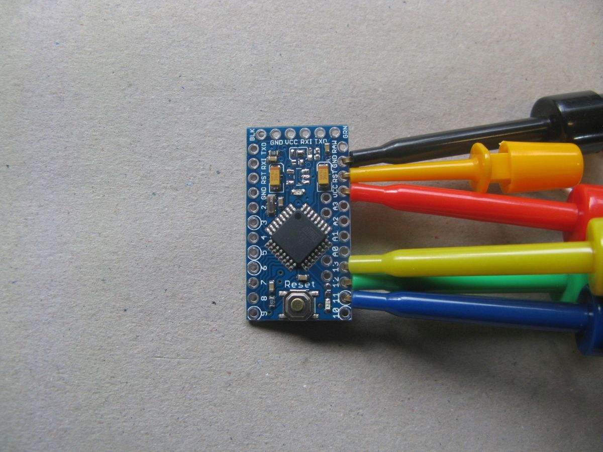
I've been looking for something quick and easy for some time. The best I've found to date are simple E-Z Hooks. They are made under several brand names. I use the mini version. The micro version I have is too small to hold a through hold.
Yeah, the wholes are through plated and usually pretty snug so not to hard to do Although if it was for something I would need to debug I would just solder on a header. You can solder the header the "wrong way around" if the larger footprint is a problem
Yep..... a spring-loaded pogo pin clothes peg system should do the trick.
Have the spring loaded pins all aligned/mounted in a row along a lightly sprung over-sized clothes peg or spring clip ..... with wires connected to each pogo pin. If the lightly sprung clip has the right clamping tension (not too strong, not too light), then the pogo pins will come down very nicely into the holes.....
If the pins are pointy, but with a wide pin diameter, then the pins should dock very nicely with each hole. The clamp method should be good for those that want to clip on and clip on fast. But the device would be customised to whatever board is being used obviously.