I am busy with a project and getting stuck on one particular part. The project is a conveyor belt driven by a stepper motor that is controlled by a sensor. When the sensor detects a part on the belt it must tell the motor to stop temporarily and then restart and continue until the next part is detected and keep doing so indefinitely.
I have managed to get to the point where the motor runs until a part is detected and then stops. The problem I am experiencing is that when the part is in the sensor's range it just stays there. I need to bypass the sensor temporarily to allow the motor to start again and then bring the sensor back online before the next part reaches it (time between parts is roughly 1 - 1.5 seconds, but that can be calibrated once running correctly).
Below is the code and the circuit for what I have explained above.
I am unsure if this can be solved simply using code or if additional electronics are required. What I have tried is to add an additional relay to the circuit that breaks one of the "LOAD" wires from the sensor and to control this relay with an output signal from the Arduino but have not been successful thus far.
One thing you need to do is note when the sensor becomes HIGH as opposed to when it is HIGH. Then use that transition to set a flag which stops the conveyor and starts/enables a timer. When the timer is done reset the flag.
Study the first five demos in: IDE -> file/examples/digital.
It looks like you'll need INPUT_PULLUP on the sensor input.
Another action. Next to the conveyor is a fiber laser engraver that writes a batch number on the part. Once the engraving is complete the belt must step forward for the next part to be engraved.
I have the LOAD wires (Black & White) connected to the coil on the relay. When the part is sensed the coil engages, sending a 5V signal coming from the 5V output on the Arduino through to Pin7.
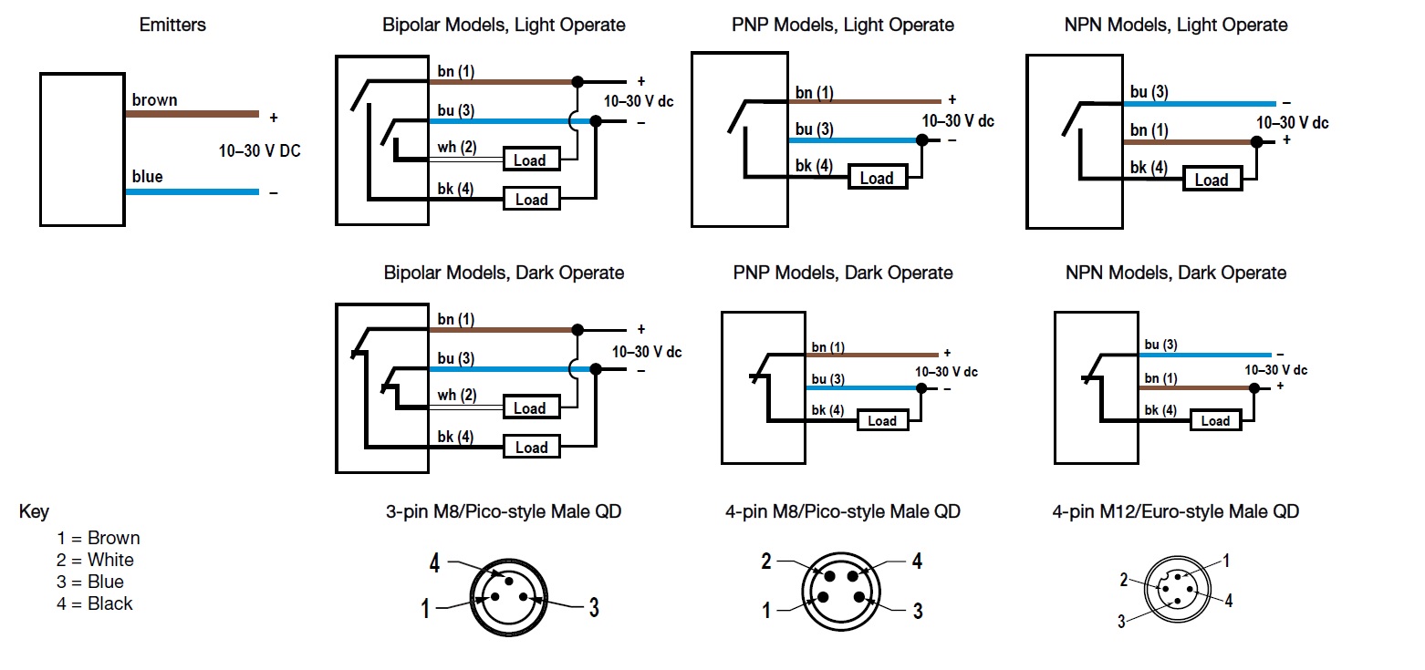
If you look at that diagram, the coil, which is your LOAD, should be between,
WHITE AND BROWN . OR
BLACK AND BLUE.
Why are you connecting between BLACK and WHITE?????
The reason that two loads are shown is because that model is PNP and NPN, you use the different outputs for the different PLC/controller input circuits you might use.
You only need to use one of the two configuration.
Relay is a NT72-2C-S10
DC5V0.45
10A 125VAC
50/60HZ
10A/250V~
10A/25V
5V
Mostly because this is my first time working with a sensor and when testing it I found that whenever it senses a part I get a 10V signal when connecting a multi meter to the LOAD wires. My thinking was then to use that 10V signal to engage the coil on the relay to let the 5V signal going to the sensor input pin (pin 7) and using "if" to tell the motor to stop when pin 7 receives a signal. A 10V relay would probably be better, but I only had the 5V relays on hand.