Hello! I'm new to electronics and I'm looking for all possible information!
I did a stationary “bicycle” project and purchased some items for the electronics…
-a mega 2560 arduino
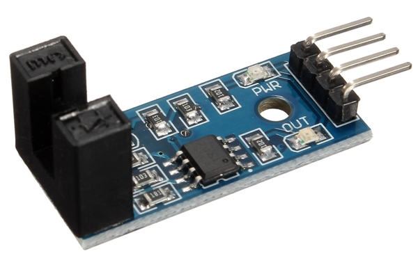
-sensor speed encoder (lm393) like this https://www.arduinoecia.com.br/wp-content/uploads/2016/02/LM393-Speed-Sensor.jpg
-a 3.5 ″ tft shield display like this https://www.filipeflop.com/produto/display-lcd-tft-shield-3-5-para-arduino/
My question is how do I use pins 22 to 53 free, since the display occupies all others ??
I've tested the shield and the sensor individually and both work. But when I use both together, the sensor doesn't work. In the sample code I took, the serial monitor shows the variation of the RPM when only the sensor is connected to the arduino. When I place the shield, I change the pin of the digital output D0 of the sensor and connect to one of the free pins of the arduino, the serial monitor is showing 0 RPM.
I change the number in this line of code to the number of the pin I connected to the sensor but it doesn't work.
How do I make it work?
int pin_D0 = 2;
int rpm;
volatile byte pulses;
unsigned long timeold;
unsigned int pulssos_por_volta = 20;
void counter ()
{
pulses ++;
}
void setup ()
{
Serial.begin (9600);pinMode (pin_D0, INPUT);
attachInterrupt (0, counter, FALLING);
pulses = 0;
rpm = 0;
timeold = 0;
}
void loop ()
{
if (millis () - timeold> = 1000)
{
detachInterrupt (0);
rpm = (60 * 1000 / pulses_for_back) / (millis () - timeold) * pulses;
timeold = millis ();
pulses = 0;
Serial.print ("RPM =");
Serial.println (rpm, DEC);
attachInterrupt (0, counter, FALLING);
}
}
Olá! Sou novo na eletrônica e estou procurando toda informação possível!
Fiz um projeto de “bicicleta” estacionária e adquiri alguns itens para a parte eletrônica…
-um arduino mega 2560
-sensor encoder de velocidade (lm393) como esse https://www.arduinoecia.com.br/wp-content/uploads/2016/02/LM393-Speed-Sensor.jpg
-um display tft de 3.5″ shield como esse https://www.filipeflop.com/produto/display-lcd-tft-shield-3-5-para-arduino/
Minha dúvida é como eu uso os pinos 22 ao 53 livres, uma vez que o display ocupa todos os outros??
Eu já testei o shield e o sensor individualmente e os dois funcionam. Mas quando eu uso os dois juntos, o sensor não funciona. No código de exemplo que peguei, o monitor serial mostra a variação do RPM quando o somente o sensor está conectado ao arduino. Quando coloco o shield, troco o pino da saída digital D0 do sensor e conecto a um dos pinos livres do arduino, o monitor serial fica mostrando 0 RPM.
Eu troco o número nesta linha de código para o número do pino que conectei ao sensor mas não funciona.
Como faço isso funcionar?