Hey so I am building a three phase voltage measurement circuit . I could measure three phase voltage using ZMPT101B module. Now I do know that zmpt101b is for single phase and max voltage of 250V on the module . Here we have 220V between L1 and Neutral and 420V between L1 and L2. So I would be connecting Phase on module to L1 and Ground on module to Neutral.
Also I noticed in the datasheet ZMPT101B Datasheet that i can just change the input voltage resistor R1 and sampling resistor R2 on the module I can measure 420V.
While i still have to run the calculations these were initial thoughts
So just wanted to check if my reasoning is proper.
Here we have 420V between L1 and Neutral and 220-240V between L1 and L2
That makes no sense.
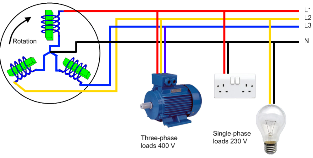
In a symmetrical three-phase four-wire wye system, the three phase conductors have the same voltage to the system neutral. The voltage between line conductors is V LL = sqrt(3) V LN
The sensor can safely measure the voltages between neutral and any of the lines is a standard three phase system.
Please post a link to an official document describing the system you are talking about.
In a symmetrical three-phase four-wire wye system, the three phase conductors have the same voltage to the system neutral. The voltage between line conductors is √3 times the phase conductor to neutral voltage:
So a 3 phase why. So if you want to know the voltage I would use 3 ZMPT 101B transformers all Line to Neutral.
Should this be a commercial application I would go with a commercial voltage transducer like this or similar. When measuring AC voltages you have a choice. Average Responding RMS Indicating which I linked to or True RMS Responding RMS Indicating like this. The ZMPT flavors give you an average response when you write your code. Assuming a perfect sine wave a ZMPT is fine.