Hi all. There is a task to write logic for three square amplitudes shifted in time and with the same frequency. I'm attaching a picture. Any ideas, I’ll be glad and grateful I need this logic by arduino cc code.
Firstly, what is the time unit mks? Microsecond?
Secondly, what Arduino are you allowed to use for this obvious assignment?
Thirdly, what is your coding experience? Have you used interrupts? Timers?
Your answers may shape guidance you will receive.
1 Like
And please explain, this did not make sense(translation?).
1 Like
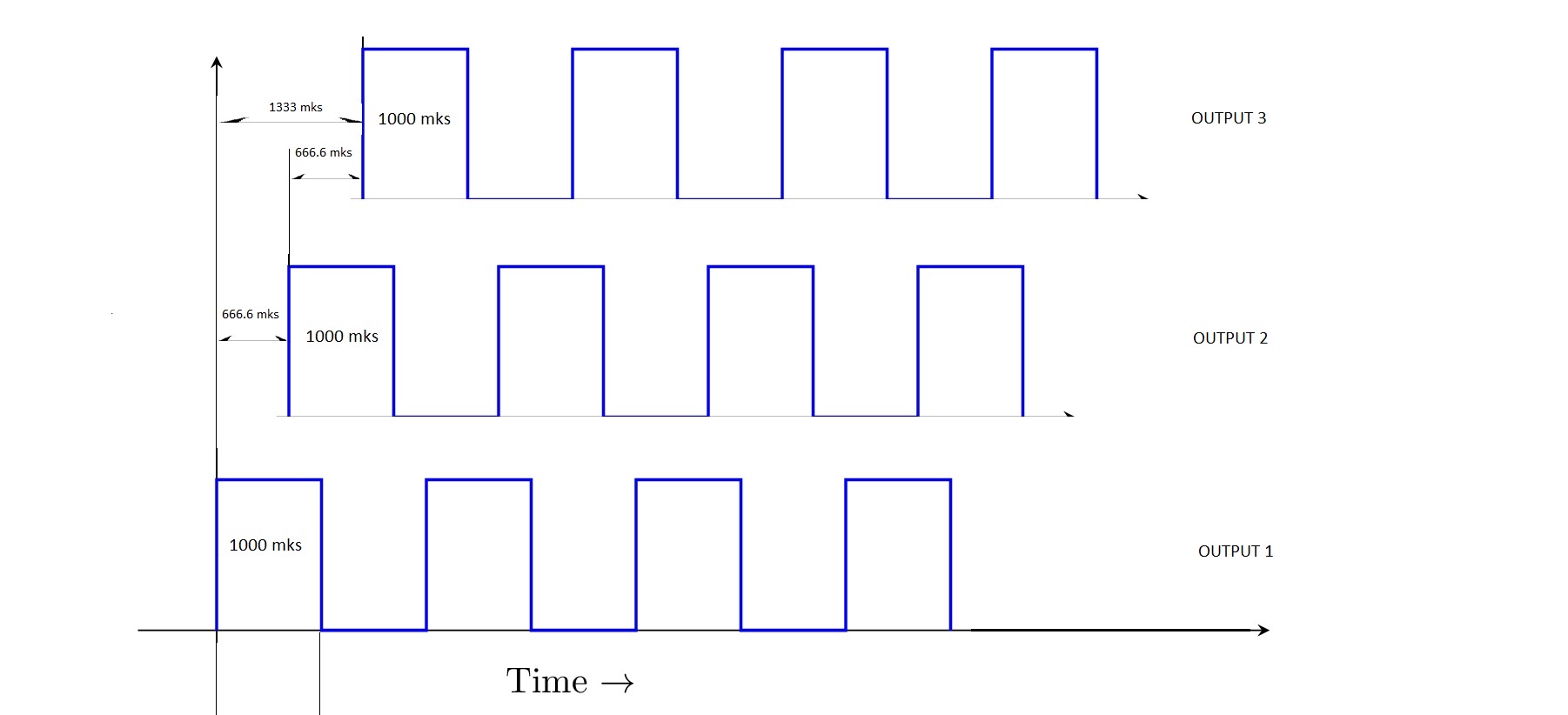
Flip the outputs every 333.3 mks in a round-robin fashion.
1 Like
Sorry my mistake, unit is mcs
time shift 666.6 µs. Take a look diagram
Guys, the time values are conditional, I need a structure in which I myself will change the numbers
You don't understand what I wrote.
Look at the diagrams, the outputs change round-robin all 333.3 units.
3 Likes
You could run this using a 333.3 us timer, cycling through a simple switch case for the 8 output states. Then, all you need to do is program the timer interval.
1 Like
Does the 4 cycles, starting, and ending sequence matter or not?
What is the trace 3 value at t=0, or the trace2 value at 800 units?
Post #2, answers pending.
In simple words, I need a code that I will download to the UNO R3 controller that will perform the function I specified in the picture
In simple words, I want to know:
- Is output 3 HIGH at t=0, and moves to LOW at t=333.3 mks.
- Are these 0.5Hz square waves?
- Or are these 500Hz square waves?
- is 0.5% accuracy OK?
- the same time possible positions
low low high
high low high
high high low....
Yes all the circle (1) divides for three pieces 0.333 each
2-3. Yes common frequency 500 Hz - Quite acceptable
If that's the way you like to think about it, you could set up a phase array like:
int phases[][3] = {
  {LOW,LOW,HIGH},
  {HIGH,LOW, HIGH},
  {HIGH,HIGH,LOW},
  ...
};
and then use:
A sloppy, rough way to do that would be something like this incomplete and completely untested snippet:
const byte Pins[] = {9,10,11};

void loop(void){
  for (int i = 0; i <7 ; ++i){
    for(int j = 0;j<3; ++j{
      digitalWrite(Pins[i],phases[i][j]);
    }
    delayMicroseconds(333);
  }
}
Or with:
maybe do the round-robin state transitions with math:
...
for (int i = 0; i <3; ++i){
   digitalWrite(Pin[i], digitalRead(Pin[i]) == HIGH? LOW : HIGH);
   delayMicroseconds(333);
}
And then if you need to improve the timing accuracy you could move to a more flexible non-blocking blink-without-delay scheme. Or if you were very picky about timing, perhaps move to using the higher resolution hardware timers and/or a Bresenham-like accumulator scheme to account for the 0.333... fractional microseconds.
Those are a few ideas.
1 Like
have a look at 3-phase-inverter-using-igbt-to-convert-dc-to-ac-voltage - may give you some ideas?
1 Like
In simple words, you want someone to write you a code that does that, correct?
There's words for that. "Paid Gig".
IF you are actually interested in coding this yourself, consider. The requested waveform doesn't actually require interrupts, if the Arduino is doing nothing else, you could get away with a series of statements in a loop, including my abovementioned switch statement.
Time for you to put something together, and ask us when you're stuck on something.
3 Likes
Three phases battery backup supply just square wave so without IGBT some different components
There are three independent outputs here. Each output has the same flip frequency of 1000 µs. The difference is that the amplitudes at the outputs are shifted to each other in time by 666.66 μs.
It's for a BLDC ?