Hello everybody,
I was trying to have a quick and dirty go at detecting pitch, roll and yaw (just to have a look of what to expect before running AHRS type of filters using libraries tha I am sure can do a much better job than I could possibly do).
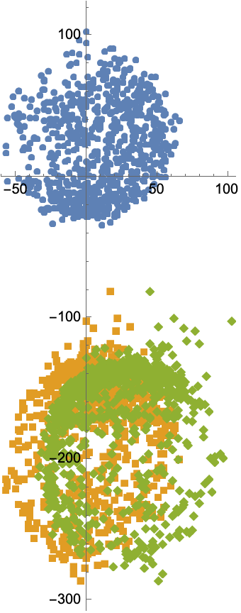
I am using a Nano BLE Sense Rev 2, and I have no problem in calculating pitch and roll and fusing them with a complimentary filter. The problem is the yaw. I have calibrated the magnetometer both for hard as well as for soft iron (not yet the gyro though, but the problem I have goes definitely beyond calibration).
Now, when I try to tilt-correct the yaw measurement I get no correction at all, and the value fluctuates quite a lot. I suspect it has something to do with the orientation of the two sensors, but I was not able to pin down the problem changing signs of the correction formulas.
I leave the sketch below just in case you can spot something that so far has escaped me.
#include <Arduino_BMI270_BMM150.h>

/* global static variables */
static float A_LOW_PASS_PARAMETER     = 0.90;
static float THETA_FUSION_PARAMETER   = 0.90;
static float PHI_FUSION_PARAMETER     = 0.90;
static float M_LOW_PASS_PARAMETER     = 0.80;

/* calibration */
static float A_THETA_CALIBRATION      = 0; /*-0.23;*/
static float A_PHI_CALIBRATION        = 0; /*0.65;*/
static float GYRO_X_CALIBRATION       = -1.23;
static float GYRO_Y_CALIBRATION       = -0.08;
static float FREE_FALL_THRESHOLD      = 0.2;

/* magnetometer */
static float M_BIAS_X =    2.48053;
static float M_BIAS_Y =   30.67026;
static float M_BIAS_Z = -199.227955;

static float SI_M_11  =  0.878218;
static float SI_M_12  = -0.014747;
static float SI_M_13  = -0.027250;
static float SI_M_21  = -0.014747;
static float SI_M_22  =  0.807423;
static float SI_M_23  = -0.033193;
static float SI_M_31  = -0.027250;
static float SI_M_32  = -0.033193;
static float SI_M_33  =  0.661987;

/* global variables */
unsigned long t_old;
bool FREE_FALL = 0;

/* accelerometer variables */
float a_x, a_y, a_z;
float a_theta_M, a_phi_M;
float a_theta_Fold = 0;
float a_phi_Fold   = 0;
float a_theta_Fnew, a_phi_Fnew;
float a_magnitude;

/* gyroscope variables */
float g_x, g_y, g_z;
float g_theta_M = 0;
float g_phi_M   = 0;
float dt;
float g_magnitude;

/* fused variables */
float theta_F = 0;
float phi_F   = 0;

/* magnetometer variables */
float m_x, m_y, m_z;
float cal_m_x, cal_m_y, cal_m_z;
float m_x_prj, m_y_prj;
float m_psi_M1,m_psi_M2,m_psi_M3;
float m_psi_Fnew;
float m_psi_Fold = 0;
float theta_F_rad, phi_F_rad;


void setup() {
  Serial.begin(9600);
  while (!Serial);
  Serial.println("Started");

  t_old = millis();

  IMU_init_and_setup();
}

void IMU_init_and_setup() {
  if (!IMU.begin()) {
    Serial.println("Failed to initialize IMU!");
    while (1);
  }

  Serial.print("Accelerometer sample rate = ");
  Serial.print(IMU.accelerationSampleRate());
  Serial.println(" Hz");
  Serial.println("Acceleration in G's");
  Serial.println();

  Serial.print("Gyroscope sample rate = ");
  Serial.print(IMU.gyroscopeSampleRate());
  Serial.println(" Hz");
  Serial.println("Gyroscope in degrees/second");
  Serial.println();

  Serial.print("Magnetic field sample rate = ");
  Serial.print(IMU.magneticFieldSampleRate());
  Serial.println(" Hz");
  Serial.println("Magnetic Field in uT");
}

void loop() {

  /* accelerometer data */
  if (IMU.accelerationAvailable()) {
    IMU.readAcceleration(a_x, a_y, a_z);

    a_magnitude = sqrt(a_x * a_x + a_y * a_y + a_z * a_z);

    /* Approximating tilt via the accelerometer */
    /* pitch */
    a_theta_M = atan2(a_x, a_z)/2/3.141592654*360 - A_THETA_CALIBRATION;
    /* roll */
    a_phi_M   = atan2(a_y, a_z)/2/3.141592654*360 - A_PHI_CALIBRATION;

    /* Apply a low-pass filter to suppress noise */
    a_phi_Fnew   = A_LOW_PASS_PARAMETER * a_phi_Fold + (1 - A_LOW_PASS_PARAMETER) * a_phi_M;
    a_theta_Fnew = A_LOW_PASS_PARAMETER * a_theta_Fold + (1 - A_LOW_PASS_PARAMETER) * a_theta_M;
    a_phi_Fold   = a_phi_Fnew;
    a_theta_Fold = a_theta_Fnew;
  }

  /* gyroscope data */
  if (IMU.gyroscopeAvailable()) {
    IMU.readGyroscope(g_x, g_y, g_z);

    /* correct for calibration */
    g_x = g_x - GYRO_X_CALIBRATION;
    g_y = g_y - GYRO_Y_CALIBRATION;

    /* define time elapsed */
    dt    = (millis() - t_old)/1000.;
    t_old = millis();

    /* Approximating tilt via the gyroscope */
    /* pitch */
    g_theta_M = g_theta_M + g_y * dt;
    /* roll */
    g_phi_M   = g_phi_M - g_x * dt;

    g_magnitude = sqrt(g_x * g_x + g_y * g_y + g_z * g_z);
  }

  /* acclerometer and gyroscope fusion through a complimentary filter */
  /* pitch */
  theta_F = THETA_FUSION_PARAMETER * (theta_F + g_y * dt) + (1 - THETA_FUSION_PARAMETER) * a_theta_M;
  /* roll */
  phi_F   = PHI_FUSION_PARAMETER * (phi_F - g_x * dt) + (1 - PHI_FUSION_PARAMETER) * a_phi_M;

  theta_F_rad = theta_F / 360 * 2 * 3.14159265;
  phi_F_rad   = phi_F / 360 * 2 * 3.14159265;

  /* magnetometer data */
  if (IMU.magneticFieldAvailable()) {
    IMU.readMagneticField(m_x, m_y, m_z);

    cal_m_x = SI_M_11 * (m_x - M_BIAS_X) + SI_M_12 * (m_y - M_BIAS_Y) + SI_M_13 * (m_z - M_BIAS_Z);
    cal_m_y = SI_M_21 * (m_x - M_BIAS_X) + SI_M_22 * (m_y - M_BIAS_Y) + SI_M_23 * (m_z - M_BIAS_Z);
    cal_m_z = SI_M_31 * (m_x - M_BIAS_X) + SI_M_32 * (m_y - M_BIAS_Y) + SI_M_33 * (m_z - M_BIAS_Z);


    m_x_prj = cal_m_x * cos(theta_F_rad) - cal_m_y * sin(phi_F_rad) * sin(theta_F_rad) + cal_m_z * cos(phi_F_rad) * sin(theta_F_rad);
    m_y_prj = cal_m_y * cos(phi_F_rad) + cal_m_z * sin(phi_F_rad);


    /* yaw/heading */

    m_psi_M1 = atan2(m_y_prj, m_x_prj)/2/3.141592654*360;
    /*m_psi_M2 = atan2(cal_m_x, cal_m_z)/2/3.141592654*360;
    m_psi_M3 = atan2(cal_m_y, cal_m_z)/2/3.141592654*360;*/


    /* Apply a low pass filter to suppress noise */
    /*m_psi_Fnew = M_LOW_PASS_PARAMETER * m_psi_Fold + (1 - M_LOW_PASS_PARAMETER) * m_psi_M;
    m_psi_Fold = m_psi_Fnew;*/
  }

  if(a_magnitude > 0 && a_magnitude < FREE_FALL_THRESHOLD) {
    FREE_FALL = 1;
  } else {
    FREE_FALL = 0;
  }

  /* magnetometer calibration */
  /*
  Serial.print("{");
  Serial.print(m_x); Serial.print(",");
  Serial.print(m_y); Serial.print(",");
  Serial.print(m_z); Serial.println("},");
  */

  /* magnetometer calibration check */
  /*
  Serial.print("{");
  Serial.print(cal_m_x); Serial.print(",");
  Serial.print(cal_m_y); Serial.print(",");
  Serial.print(cal_m_z); Serial.println("},");
  */


  Serial.print(a_theta_M);
  Serial.print('\t');
  Serial.print(a_phi_M);
  Serial.print('\t');
  Serial.print(a_theta_Fnew);
  Serial.print('\t');
  Serial.print(a_phi_Fnew);
  Serial.print('\t');
  Serial.print(theta_F);
  Serial.print('\t');
  Serial.print(phi_F);
  Serial.print('\t');
  Serial.println(m_psi_M1);
  /*Serial.print('\t');
  Serial.print(a_y);
  Serial.print('\t');
  Serial.println(a_z);
  Serial.print('\t');
  Serial.print(g_x);
  Serial.print('\t');
  Serial.print(g_y);
  Serial.print('\t');
  Serial.print('\t');
  Serial.println(m_psi_M1);*/

  delay(100);

}