BLE Sense Rev2 IMU & Magnetometer Sensor Fusion - values drift, what is the correct axis orientation for BMI270/BMM150?

I have a Arduino Nano BLE Sense Rev2, so far working with the new version of BLE sense has not been a fun experience considering the limited tutorials for the on board IMU.

I'm sorry I am no expert in the theory of sensor fusion or AHRS, but I know that if the output drifts or responds slowly, it must be the orientation of either sensors not aligning. I am currently using the SensorFusion Madgwick algorithm to fuse the sensor values.

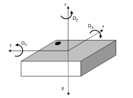
There was already a thread on this issue on Madgwick sensor fusion with Sense Rev2. But didn't seem to help me. I tried the advice on figuring out the orientation of the IMU and the magnetometer, I found out that the axes lined up the same way as the ICM-20948 shown in the answer (not the notch, but the magnetometer Y and Z being inverted in respect to the IMU). Below is the picture from the Nano BLE Sense Rev2 chip layout, BMI270 and BMM150 datasheet respectively.


image
image

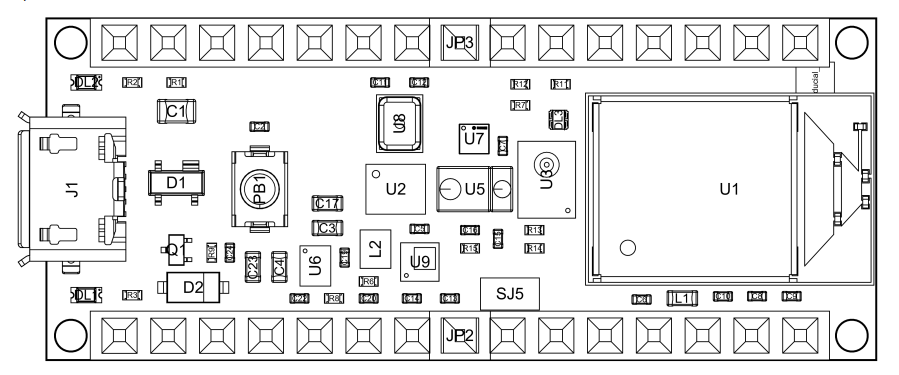
In the chip layout, U2 is BMI270 and U7 is BMM150, and the notch is aligned, so the magnetometer Y and Z axis is inverted. So I apply the corrected the value and apply it as per the answer, and the code is as below.

#include "Arduino_BMI270_BMM150.h"
#include "SensorFusion.h"

SF fusion;
float ax, ay, az, gx, gy, gz, mx, my, mz;
float deltat;

void setup() {
  Serial.begin(9600);
  while (!Serial);
  Serial.println("Started");

  if (!IMU.begin()) {
    Serial.println("Failed to initialize IMU!");
    while (1);
  }
}

void loop() {
  if (IMU.gyroscopeAvailable()) {  IMU.readGyroscope(gx, gy, gz);  }
  if (IMU.accelerationAvailable()) {  IMU.readAcceleration(ax, ay, az);  }
  if (IMU.magneticFieldAvailable()) {  IMU.readMagneticField(mx, my, mz);  }

  ax *= 9.80665; ay *= 9.80665; az *= 9.80665;
  gx *= PI / 180; gy *= PI / 180; gz *= PI / 180;

  deltat = fusion.deltatUpdate();
  fusion.MadgwickUpdate(gx, gy, gz, ax, ay, az, mx, -my, -mz, deltat);

  char data[100];
  sprintf(data, "%.2f\t%.2f\t%.2f\n", fusion.getRoll(), fusion.getPitch(), fusion.getYaw());
  Serial.println(data);
}

The values reflected the opposite way of the rotation before slowly reaching the desired value, it took like 10 seconds, so I believe something is still wrong.
The best result I got so far is by inverting the accelerometer z axis, and got the most stable results so far, but the yaw drifts for a while after rotating to an angle.

fusion.MadgwickUpdate(gx, gy, gz, ax, ay, -az, mx, my, mz, deltat);

I also doubt this is the right way. I'm not sure whether the alignment is still wrong, maybe the magnetometer needs calibration (idk but I also tried isolating it from any nearby source of metal) or maybe it's just that slow, because I also tried Reefwing AHRS the values responds too slow that I am no longer using it, but it was also explained there that the BMI270/BMM150 library is giving a slow update.

Thanks in advanced.

You have the right idea, but keep in mind that the The Earth's "North" pole is a south magnetic pole and that for accelerometers, the acceleration due to Earth's gravity is measured as "up", along the positive Z axis.

You need to double check your assignment of axes by printing out the raw magnetometer measurements. In the mid-latitudes of the northern hemisphere, the Earth's magnetic field points rather steeply down into the ground. Look up the details for your geographic location on line. Make sure that after any axial changes you make, the raw data correctly represents the direction of the Earth's field vector.

This won't work:

fusion.MadgwickUpdate(gx, gy, gz, ax, ay, -az, mx, my, mz, deltat);

The mag/accel axial assignments are both right-handed as defined by the manufacturer, and any swaps or sign changes you make must maintain that right-handedness. The above defines a left-handed accelerometer axial system.

BTW, the magnetometer and the gyro must be calibrated or nothing will work.

If the dots on the ICs are in the same orientation on the the PCB, I suspect that the correct axis reassignment is this one:

fusion.MadgwickUpdate(gx, gy, gz, ax, ay, az, mx, -my, -mz, deltat);

The rate gyro measurements must be scaled to radians/second.

So I just calibrated both the gyro and magnetometer, code attached below. It doesn't seem to improve the yaw, but the roll and pitch angle seems more stable but I think that was due to the gyro.

For the calibration, since there are no official method, I calibrated it using Matlab magnetometer calibration fucntion using matlab script. Then I copied the soft iron and hard iron correction values into arduino.

How do I determine the right axes by using the raw values? Can you elaborate or point out a source.

If you mean the magnetic declination, I just updated that in the code. After calibrating with Matlab, I was also given "Expected magnetic field strength" I'm not sure what it means but after digging some info I found out it has something to do with normalization scaling, and so i added that as well. Overall I'm not sure of both the magnetic declination and scaling function that I made in the code, please take a look.

Is this why when I pointed X axis towards north it reads 180 degree? Btw I also found out that the yaw value is stable as it comes close to 360, between 300-360. I'm not sure why, but felt like there's a conflict between [-180, 180] and [0, 360] range.

I also found out that the configuration below also gives stable values (again except yaw)

fusion.MadgwickUpdate(-gx, gy, gz, -ax, ay, az, mx, my, mz, deltat);

Used this mainly due to examples I found, but from this example on matlab using MPU9250 I found out that all the accelerometer axis are inverted in respect to the magnetometer, I which what this configuration represents I suppose.

I did that in the code didn't I? The raw reading from the library is said to be in degree/s

#include "Arduino_BMI270_BMM150.h"
#include "SensorFusion.h"

SF fusion;
float ax, ay, az, gx, gy, gz, mx, my, mz;
float gyroXOffset = 0, gyroYOffset = 0, gyroZOffset = 0;
float deltat;

//Expected magnetic field strength (uT)
float M_scale = 27.4584;

//hard-iron offset
float M_B[3]
{-27.53679457, -0.2111695583, -27.52377034};

//soft-iron scale correction
float M_Ainv[3][3]
{{  1.0080,  -0.0186, 0.0695},
{  -0.0186,  0.9447, 0.0119},
{ 0.0695, 0.0119, 1.0555}};

void updateMag(float& mx, float& my, float& mz){
  float temp[3];

  temp[0] = (mx - M_B[0]);
  temp[1] = (my - M_B[1]);
  temp[2] = (mz - M_B[2]);

  mx = M_Ainv[0][0] * temp[0] + M_Ainv[0][1] * temp[1] + M_Ainv[0][2] * temp[2];
  my = M_Ainv[1][0] * temp[0] + M_Ainv[1][1] * temp[1] + M_Ainv[1][2] * temp[2];
  mz = M_Ainv[2][0] * temp[0] + M_Ainv[2][1] * temp[1] + M_Ainv[2][2] * temp[2]; 
}

void applyScalingFactor(float& mx, float& my, float& mz, float expectedFieldStrength) {
    float currentMagnitude = sqrt(mx * mx + my * my + mz * mz);
    float scaleFactor = expectedFieldStrength / currentMagnitude;

    mx *= scaleFactor;
    my *= scaleFactor;
    mz *= scaleFactor;
}

void applyMagneticDeclination(float& mx, float& my, float declination_deg) {
    float declinationRad = declination_deg * (PI / 180.0);
    float mx_corrected = mx * cos(declinationRad) - my * sin(declinationRad);
    float my_corrected = mx * sin(declinationRad) + my * cos(declinationRad);

    mx = mx_corrected;
    my = my_corrected;
}

void calibrateGyro(){
  Serial.print("calibrating gyroscope...");
  const int numSamples = 3000;
  float sumX = 0, sumY = 0, sumZ = 0;

  int actualSample = 0;
  for (int i = 0; i < numSamples; i++) {
    if (IMU.gyroscopeAvailable()) {  IMU.readGyroscope(gx, gy, gz);  }            // deg/s
    else{continue;}
    sumX += gx; sumY += gy; sumZ += gz;
    delay(3);
    actualSample++;
  }

  gyroXOffset = sumX / actualSample;
  gyroYOffset = sumY / actualSample;
  gyroZOffset = sumZ / actualSample;

  Serial.println("Finished");
  Serial.println(actualSample);
  Serial.println(gyroXOffset);
  Serial.println(gyroYOffset);
  Serial.println(gyroZOffset);
}

void setup() {
  Serial.begin(9600);
  while (!Serial);

  if (!IMU.begin()) {
    Serial.println("Failed to initialize IMU!");
    while (1);
  }

  calibrateGyro();
  Serial.println("Started");
}

void loop() {
  if (IMU.gyroscopeAvailable()) {  IMU.readGyroscope(gx, gy, gz);  } else {return;}            // deg/s
  if (IMU.accelerationAvailable()) {  IMU.readAcceleration(ax, ay, az);  } else {return;}     // g
  if (IMU.magneticFieldAvailable()) {  IMU.readMagneticField(mx, my, mz);  } else {return;}   // uT

  gx -= gyroXOffset;
  gy -= gyroYOffset;
  gz -= gyroZOffset;

  updateMag(mx, my, mz);
  applyScalingFactor(mx, my, mz, M_scale);
  applyMagneticDeclination(mx, my, -0.19);  //using the magnetic declination of my location (Kuala Lumpur, Malaysia)

  ax *= 9.80665; ay *= 9.80665; az *= 9.80665;            // m/s2
  gx *= PI / 180.0; gy *= PI / 180.0; gz *= PI / 180.0;   // rad/s

  deltat = fusion.deltatUpdate();
  fusion.MadgwickUpdate(-gx, gy, gz, -ax, ay, az, mx, my, mz, deltat);

  char data[100];
  sprintf(data, "%.2f\t%.2f\t%.2f\n", fusion.getRoll(), fusion.getPitch(), fusion.getYaw());
  Serial.println(data);
}

Since I'm not sure of both the magnetic declination and scaling function I made, I tried with either the magnetic declination or scaling function, and without both (in case both are wrong) and it still doesn't work and no major improvement on the result.

I also just knew that the sampling frequency is 10Hz, so not all the loop iteration will end up reading a value, so I updated it so that it returned the loop if values is not given to avoid messing up the update values. But again no significant changes.

It is mathematically impossible for that to work correctly, because -ax changes the handedness of the coordinate system. Garbage in, garbage out.

How do I determine the right axes by using the raw values?

By using common sense. You should know the direction of the Earth's magnetic field in your vicinity, and the correct axial assignment will produce a set of raw values that point in that direction. Same for the accelerometer -- when held still, the acceleration due to gravity is vertically up.

So, that would mean if i were to hold the positive x-axis towards north, it should read max value and the opposite towards south? If this is what you mean, I tested this (with calibration applied) using axis orientation frame (as per datasheet picture) as reference.

X-axis pointed north = 27uT
X-axis pointed south = -27uT

Y-axis pointed north = -27uT
Y-axis pointed south = 27uT

Z-axis pointed north = 27uT
Z-axis pointed south = -27uT

I spun around each axis to make sure they were the right axes as per labelled.
Now what do these say about the axis assignment? It looks to me that Z doesn't need to be inverted, but idk, I'm pretty much confused by now. Let me know if more details are needed.

What you did above is correct. However, as the sensor ICs are mounted on the PCB, the magnetometer and accelerometer Z axis definitions disagree, and that has to be corrected or the fusion algorithm simply won't work.

After carefully reviewing the data sheets for the two sensors, and assuming that the code does not change the default mapping of the sensor axes, I am fairly certain that the correct remapping of the magnetometer data is this one:

fusion.MadgwickUpdate(gx, gy, gz, ax, ay, az, mx, -my, -mz, deltat);

That may not be the only problem with the code you posted, though. If the sensor calibration was not correctly done or was incorrectly applied ...

BTW the Reefwing AHRS library is clearly wrong, because only the magnetometer y axis is inverted. That also invalidates the fusion math.

This topic was automatically closed 180 days after the last reply. New replies are no longer allowed.