After a day or two of very frustrating troubleshooting, I think I've discovered something unexpected. I used a 3.3V Pro-Mini board and some other analog hardware to build an accurate MilliOhm meter with an autozero function. It's powered by two AAA Lithium batteries, powering Vcc directly.
During Setup, I use the analogReference(INTERNAL); statement to select the 1.10V reference. The design of the code and circuitry is such that it measures the resistance across a pair of terminals by reading the voltage drop with a 100mA constant current source applied. The reading at startup (during Setup) is done with the test leads shorted, so as to measure and establish the "offset" resistance of the test leads, so that it can later be subtracted from the actual reading of the unknown resistance.
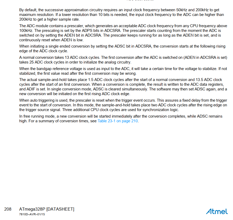
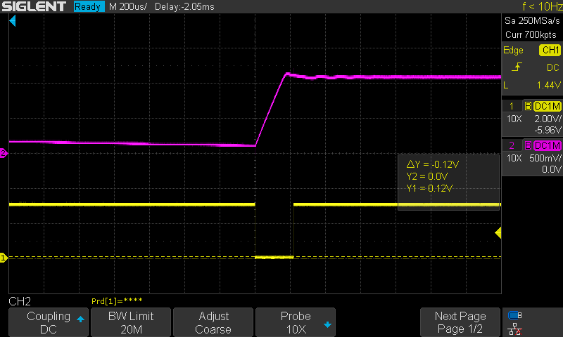
The auto-zero feature wasn't working properly, so I resorted to looking at the reference pin of the atmega328 with a scope, while also monitoring the digital output that enables the current source. What I found was that, even though the analogReference(INTERNAL); statement occurs immediately after entering Setup, the reference voltage didn't drop from Vcc to 1.10V until a few seconds later when the first analogRead() occurred. This meant that the reference voltage was dropping just as I was reading the A/D, which of course caused huge errors. (No, I didn't add any caps to the Ref pin)
I verified this (and fixed the problem) by adding a "dummy" analogRead() statement several seconds before I actually needed it.
I was wondering if others had discovered this, and if this is documented somewhere. Did I make some mistake somewhere? My code (which is working fine now) is below.
// This is a Milli-Ohm meter. It can measure resistance from 1 mOhm to 11.00 Ohms, using a Pro-Mini board (3.3V),
// a 100mA constant current source (LT1635) and a diff amp with a gain of ten (TLV9151) to gain-up the voltage drop across the load.
// The current source is turned on for a short time, and the voltage drop across the terminals is measured and gained-up by 10.
// The resistance is calculated and displayed on an OLED display.
// There is an auto-zero phase at startup that allows the lead resistance (and any internal offsets) to be zero'd out.
// Modified the auto-zero code and added an auto-range feature to measure resistances up to 11.00 Ohms.
// Had to add a "dummy" analog read a few seconds before it was need to "wake-up" the internal reference!
// Rev 2.0, 1/20/2024, D. Salerno

#include <Wire.h>  // Library for I2C communication
#include <Adafruit_GFX.h>
#include <Adafruit_SSD1306.h>
#define SCREEN_WIDTH 128  // OLED display width, in pixels
#define SCREEN_HEIGHT 64  // OLED display height, in pixels
Adafruit_SSD1306 display(SCREEN_WIDTH, SCREEN_HEIGHT, &Wire, -1);

float rev = 2.0;     // This is the revision of the code
float vref = 1.110;  // This is the actual internal reference voltage
float gain = 10.05;  // This is the diff-amp gain
float ICC = 0.101;   // This is the constant current pulse, in amps
int enable = 10;     // This is D10 (pin 13), used as an output to enable the current source
int t1 = 2;          // This is the current pulse duration in msec
int t2 = 1000;       // This is the measurement period in msec
int count = 0;       // This is the A/D count when reading the isense input
int bigcount = 0;    // This is the A/D count when reading the bigsense input
float offset = 0;    // This is the measured offset, at Startup, which is subtracted from the measured resistance
int isense = A0;     // This is the A/D input pin that is used
int bigsense = A1;   // This A/D input is used when the resistance is > 1.1 Ohms (from before the gain of 10 amp)

float resistance;    // This is the calculated resistance in Ohms
int Vc = 9;          // This is the digital input (pin 12) for monitoring the collector voltage of the current sink, to check for a load

// This measures the battery voltage at Startup, without needing a resistor divider
long readVcc() {  // This measures the Vcc voltage, using the internal reference to compare it to
  ADMUX = _BV(REFS0) | _BV(MUX3) | _BV(MUX2) | _BV(MUX1);
  delay(20);  // Allow time for the reference to settle
  ADCSRA |= _BV(ADSC);
  while (bit_is_set(ADCSRA, ADSC));
  long result = ADCL;
  result |= ADCH << 8;
  result = 1135530L / result;  // Back-calculate AVcc in mV (1.1V * 1023 * 1000)
  return result;
}

void setup() {
  analogReference(INTERNAL);    // Use the internal 1.10V reference for the A/D
  display.begin(SSD1306_SWITCHCAPVCC, 0x3C);
  Serial.begin(9600);
  pinMode(enable, OUTPUT);  // Declare the digital output that will enable the current source
  pinMode(Vc, INPUT);       // Declare the digital input that monitors the collector voltage
  display.setTextSize(2);
  display.setTextColor(WHITE);
  display.clearDisplay();
  float Vcc = readVcc();        // gives the Vcc voltage in mV
  display.setCursor(0, 0);      // (X pos, Y pos) Start the text in the upper left-hand corner (indented in a bit)
  display.print(Vcc / 1000, 2); // Display the voltage in volts, with two decimal places
  display.println(" V");
  display.print("Rev ");
  display.println(rev, 1);
  display.println("1/20/2024");
  display.display();
  delay(2000); //
  display.clearDisplay();
  display.setCursor(0, 0);      // Start the text in the upper left-hand corner (indented in a bit)
  display.println("Begin");     // Begin the Autozero routine
  display.println("Auto-zero"); // Short the test leads together
  display.display();
  count = analogRead(isense);   // This is a "dummy" Read to wake up the reference a few seconds before the real Read!
  delay(2000);
  digitalWrite(enable, HIGH);   // Turn on the current source
  display.clearDisplay();
  display.setCursor(0, 18);     // Start the text in the upper left-hand corner (indented in a bit)
  display.println("Short the"); // Begin the Autozero routine
  display.println("Leads");     // Short the test leads together
  display.display();
  while(digitalRead(Vc) == HIGH) {  // Wait for the test leads to be shorted, which will make Vc Low
    delay(100);
   }
  delay(2000);                  // Allow time to short the leads and "settle" before taking the reading
  count = analogRead(isense);   // Read the analog input pin that monitors the gained-up voltage drop
  delay(10);                    // Probably don't need a delay here
  offset = (count * vref / (1023  * gain * ICC));  // Calculate the offset resistance
  Serial.print("Offset = ");
  Serial.print(offset, 3);
  Serial.println(" Ohms");
  digitalWrite(enable, LOW);    // Turn off the current
  delay(1000);
  display.clearDisplay();
  display.setCursor(0, 0);      // Start the text in the upper left-hand corner (indented in a bit)
  display.println("Remove");
  display.println("Short");
  display.display();
  delay(1500);
  display.clearDisplay();
  display.setCursor(0, 0);      // Start the text in the upper left-hand corner (indented in a bit)
  display.println("Offset = "); // Display the measured offset resistance
  display.println(offset, 3);   // Display the measured offset, with fixed decimal places
  display.println("Ohms");
  display.display();
  delay(2000);
}

void loop() {
  digitalWrite(enable, HIGH);      // Turn on the current source
  delay(t1/2);                     // Wait (t1/2) milliseconds, so that you sample in the middle of the pulse
  count = analogRead(isense);      // read the analog input pin that monitors the gained-up voltage drop
  delay(1);                        // Allow time between A/D readings
  bigcount = analogRead(bigsense); // Read the voltage before the gain of 10 amp
  delay(t1/2);                     // Probably don't need a delay here
  digitalWrite(enable, LOW);       // Turn off the current source
  display.clearDisplay();
  display.setCursor(0, 0);         // Start the text in the upper left-hand corner (indented in a bit)
  if (count < 1022) {              // For resistances less than 1.1 Ohms
    resistance = (count * vref / (1023 * gain * ICC)) - offset;
    display.println("Resistance");   //
    display.println(resistance, 3);  // Display the measured resistance, with fixed decimal places
    display.println("Ohms");
    display.display();
  }
  else if (count >= 1022 && bigcount < 1022) {
    resistance = (bigcount * vref / (1023 * ICC)) - (offset);
    display.println("Resistance");   //
    display.println(resistance, 2);  // Display the measured resistance, with fixed decimal places
    display.println("Ohms");
  }
  else {
    display.println("Resistance");
    display.println("> 11 Ohms");
  }
  display.display();
  delay(t2);  // Wait before taking another reading
}