Hello all,
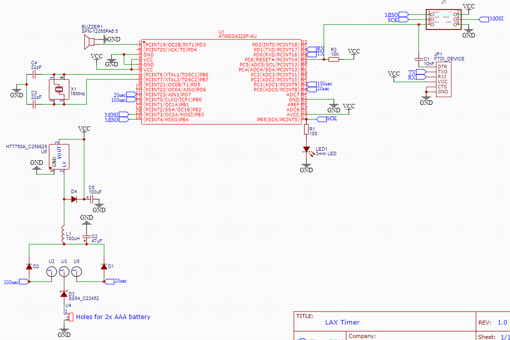
I have created a prototype board for my dual timer. It has a 3 position switch so that users can choose between two different times. This is my first time creating a PCB circuit and there seems to be many flaws and inefficiencies. I have attached my version 1 schematics. There are two changes I have already made for version 2 (switch from crystal resonator to oscillator and increase resistance on led resistor).
Even though this circuit works as is, I have concerns about expanding on it because the power management seems to be performing at the bare minimum. With 2 fresh aaa batteries (all I can fit) the converter is putting out 3.3v with the led on and 3.8v with it off (I was intending to run on 5v). I choose these parts on my own without a great ability to understand the datasheets. Looking back the D3 diode probably isn't necessary for reverse current protection so I will likely remove it. After the switch is turned on it goes through either D1 or D2(SM4007PL). I measured the input to be 2.3v and the output to be 1.5v of the active side diode. For the voltage boost, I choose the HT7750a because it is available on JLCPCB's SMD service. I copied the test circuit on the datasheet and added the 100uH inductor, 47uF and 22uF capacitors and diode (I used B5819W).
Any suggestions for improving this circuit would be much appreciated.