Hey everyone, I was wondering how could i construct an LED clock attached below.. I did some research and came across TLC5925 which worked soley for this type of clock. I know only basic arduino programming and I'm a Computer Science student and wish to do this as mini project. Could you please help me in learning more about connections and coding part of TLC5925. Thank you ![]()

Where did you find this project ?
Have you Googled this subject yet ?
Did you find this ?
which (if you click on "hacked gadgets" INSTEAD of "arduino clock", leads to THIS:
http://hackedgadgets.com/2012/08/12/rgb-arduino-led-clock/
which leads to this:
http://hackedgadgets.com/alan-parekh-hacked-gadgets-author/comment-page-2/#comment-1647961
This is useless because the resolution is so bad the schemtics are unreadable:
http://electronprojects.blogspot.ie/p/arduino-led-clock.html
At the bottom where it says "Links" there is no link (that works).
BOTTOMLINE:
I can't find the code or a usable schematic. All I can find is lots of photos of the clock.
raschemmel:
At the bottom where it says "Links" there is no link (that works).
BOTTOMLINE:
I can't find the code or a usable schematic. All I can find is lots of photos of the clock.
The links work, it link to Google Doc. to clock.rar had all the files "Eagle files, HEX & Arduino code + script for LED placement & rotation"
Clock.rar (184 KB)


[quoteauthor=BillHo link=topic=261353.msg1845045#msg1845045 date=1408244563]
raschemmel:
At the bottom where it says "Links" there is no link (that works).
BOTTOMLINE:
I can't find the code or a usable schematic. All I can find is lots of photos of the clock.
The links work, it link to Google Doc. to clock.rar had all the files "Eagle files, HEX & Arduino code + script for LED placement & rotation"
[ / quote]
yes the link actually worked and i had downloaded clock.rar earlier but i couldn't understand much. Could someone please walk me through the basics of this stuff as in connections, programming . Thanks in advance ![]()
And you didn't think to tell us you already had a link to all the documentation ?
I don't know why but I couldn't open the clock.rsr file. Can zomeone upload the clock.rar file ? I can open .rar files but all I found was a.html file. No archive.
raschemmel:
And you didn't think to tell us you already had a link to all the documentation ?
I don't know why but I couldn't open the clock.rsr file. Can zomeone upload the clock.rar file ? I can open .rar files but all I found was a.html file. No archive.
Clock.rar (184 KB)
Cool design ![]()
I managed to read the rar file ok. Basically there are 9 P-channel mosfets supplying the high side (RGB for each of hour,min,sec) and then 180 low side channels (60 for each of hour,min,sec) controlled by 5925s, plus another two 5925 driving 4 digit 7 segment leds.
The PCB is 20cm diameter, so it would cost $20/PCB at cheap suppliers like iteadstudio.
@ Billho & Sugosh,
Thanks for uploading those files. I was able to download and open everything (except the board files because I don't have Eagle).
I don't know if anyone notice the digitalWriteFast Library ? (in the code)
Library link:
https://code.google.com/p/digitalwritefast/downloads/list
According to Reply#1 in this post, you don't have to worry about this :
#include <avr/wdt.h>
For anyone who plans to include the DHT11,
The PWM for every LED is overkill.
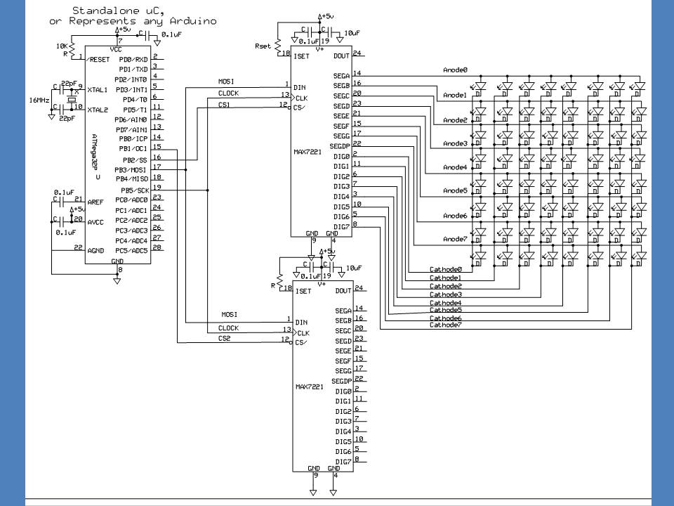
Two MAX7219 can drive 128 LEDs with 15 levels of brightness control.
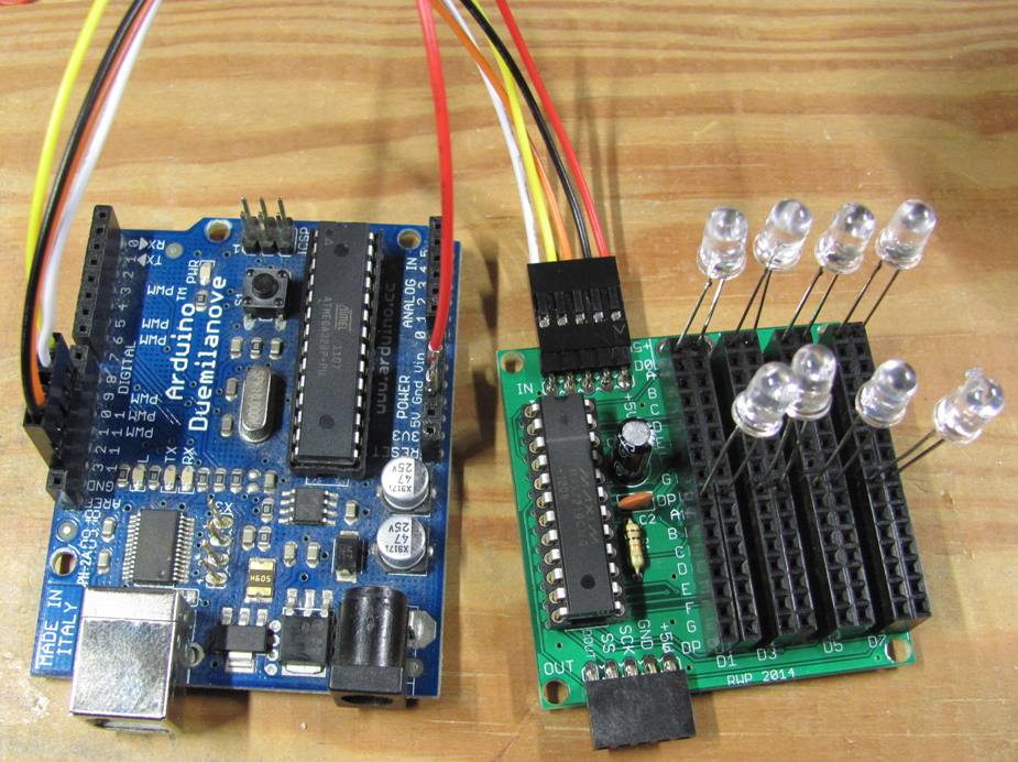
I have this little breakout board that allows individual LEDs to be connected and then spaced out as needed.
http://www.crossroadsfencing.com/BobuinoRev17/
Or just wire up 2 MAX7219s per the attached schematic, keeping the matrix wiring intact.
A 16 byte array is then used to keep track of which LEDs are on/off on a second by second basis, and send the updated bytes to the MAX7219s using SPI.transfer.
Pretty straightforward.