I've been trying to get the TMC2209 to work with a SAMD chip and this thread has been the most useful resource. I'm able to drive step and direction but I can't receive which I need to in order to use the StallGuard feature.
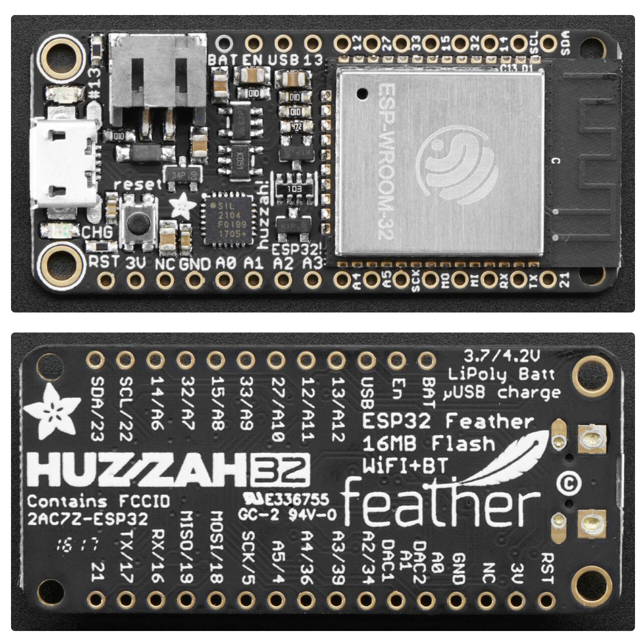
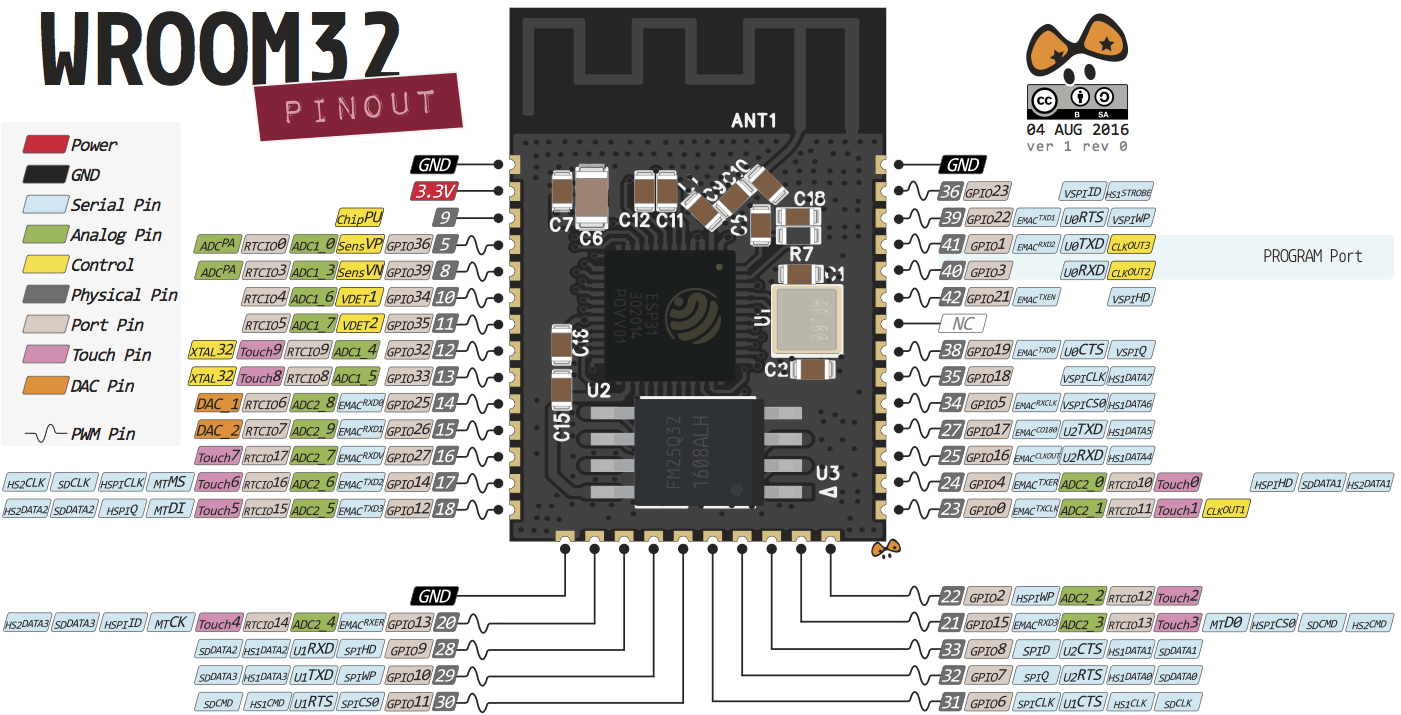
I'm using an Adafruit HUZZAH32 for my microcontroller. Here are the pinouts for the HUZZAH:
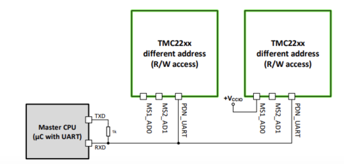
There is a 1k-resistor that creates a connection from TX to Rx.
Is this really according to the specification on how to communicate with a TMC2209-stepper-driver?
I can't say that I have worked with thousands of different serial devices but to me this 1k-resistor looks pretty akward.
Did you look up the datasheet of the TMC2209 if this is correct?
best regards Stefan
Aha. OK learned something new.
Did you try to use one of the example-codes from the TMCStepper-library?
I have looked up the adafruit documentation
It says that
The TX pin is the output from the module. The RX pin is the input into the module. Both are 3.3V logic
So my guessing is in the TMC-2209-Datasheet the naming of the Rx/Tx-pins is based on the view of the microcontroller.
This would mean that you have to connect the wire from the HUZZA32-board from IO-pin named Rx which is the third one from right to left
While you have connected it to the second (which is the Tx-Pin)
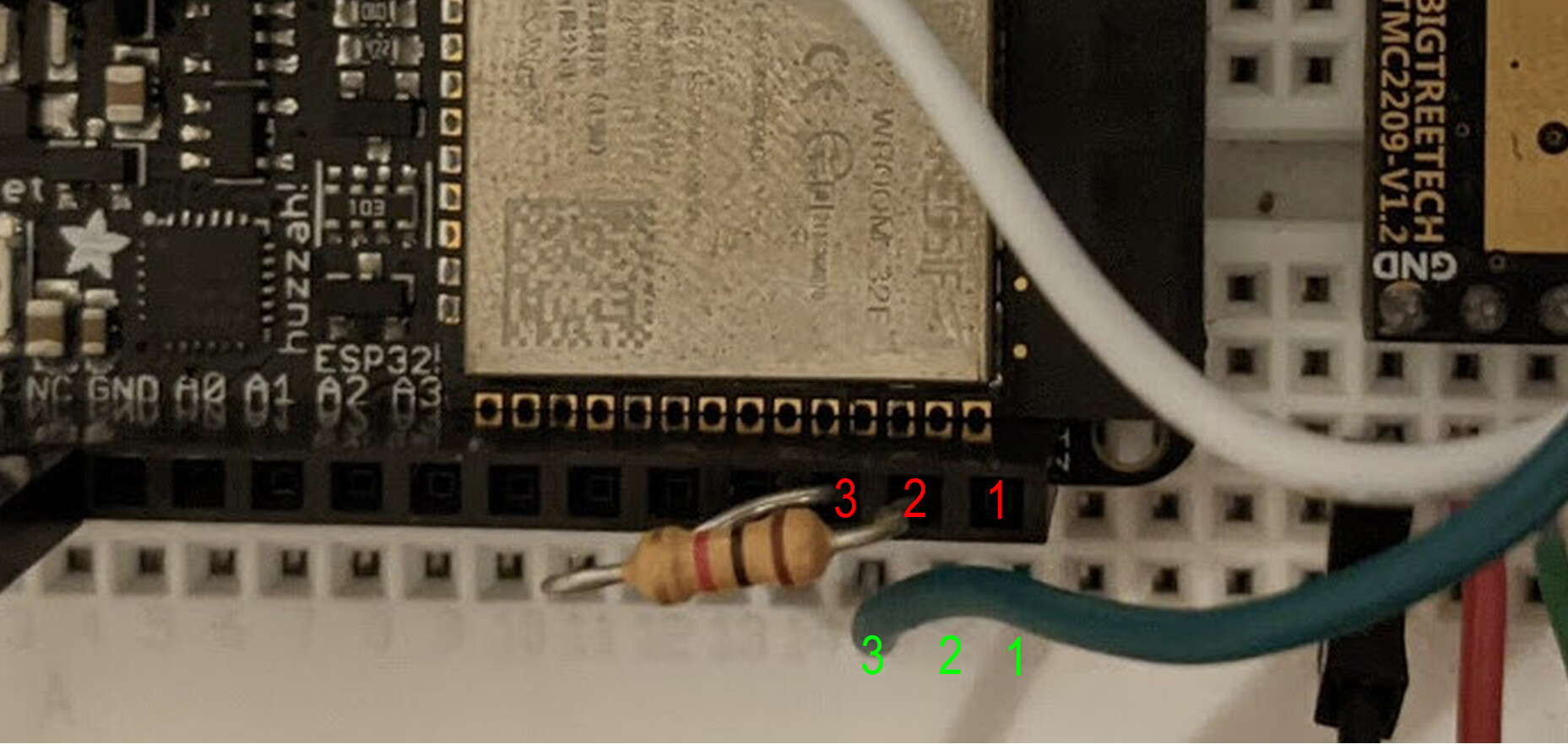
Though it might be possible that you have it connected right.
As long as a picture is taken from not direct above it is hard to see
So I added green numbers 3,2,1 that count the wholes of the bread-board
and red numbers 3,2,1 that count the wholes of the Huzza32-female-header
So please clear up which description is correct by a precise description using the colored numbers.
Do you happen to have an additional virtual-com-port USB-to-serial-converter you could connect to the TMC-2209
or do you have a logic analyser that could be used for analysing?
Thanks Stefan! You've got a good eye I also paused while doing the wiring because it was somewhat unclear how things lined up. It's wired as your last annotated picture suggests (3 to 3, 2 to 2) with the wire to the TMC going from the RX pin. I have tried some of the example programs from the library but no luck. I should have access to some better troubleshooting equipment in a few weeks. What would you recommend I check for?
You can use them with a freeware called Zadic PulseView.
PulseView can record the bitbanging of a lot of buses like onewire I2C, UART etc. and decode it!
and a USB virtual comport. I recommend one with a micro USB-connector that could be connected with any USB-smartphone-data-cable
You could use the virtual-comport to send commands towards the TMC2209 to see if it reacts then. And you could connect the Rx-Pin in parallel to your arduino to read the signals send towards the TMC2209 or towards the Arduino.
Not the ones with a USB-A plug soldered to the PCB. Those will tend to bend and brake the plug
most professional would be a two channel or four channel digital storage oscilloscope but they are quite expensive
best regards Stefan
See page 17 of datasheet UART Single Wire Interface Datagram Structure for Read Access and Write Access. Most importantly you must append each datagram with CRC Calculation for CRC8-ATM polynomial = 𝑥8 +𝑥2 +𝑥1 +𝑥0.
Datagram structure is 64bits excluding UART Start and Stop bits.
Remember reading any register on the TMC2209 only requires 32bits ie 4 UART bytes send to the driver chip, if 8bit CRC is correct the TMC2209 will respond with a 64bits ie 8 UART bytes of which 4 bytes are the register contents you requested.
Your first byte is a UART sync, it tells the TMC2209 what baud rate you are going to communicate with, looks like so in bits [10101010] actual UART byte, have intentionally left out Start and Stop bits. Actually the datasheet requires the first 4 bits/Nibble to be 1010, remaining four can be any state.
Your second UART byte is the TMC2209 address you setup on the MS1 & MS2 pins if all 3 or 4 stepper drivers are on the same party line. 1st driver = 00, 2nd = 01, 3rd = 10 & 4th = 11, this way on a common UART wire all four drivers can be individually addressed.
Your third UART byte is TMC2209 register address 7bits + read/Write bit. To read a register clear this bit and set it if you intend to write to it. This gives you 0x00 - 0x7F addressable registers, but not all are implemented.
Your fourth and last UART byte is 8bit CRC for UART data error checking especially useful when you wire up these stepper drivers on an RS-485 line.
Next is the response from TMC2209 with 8 UART bytes 64bits in all.
Kindly check the datasheet for concise structure of receive datagram.
Your main issue is that you are trying to use UART1, you should be using UART2. UART1 is used by the USB interface.
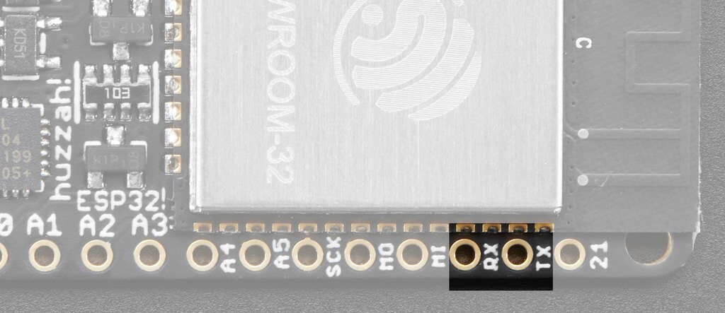
So : #define SERIAL_PORT Serial2
The pins are the same as in the ESP32 chip, GPIO16 & GPIO17 are UART2. Notice U2 TX & U2 RX. So you have the wires connected correctly. But you had just defined the wrong UART port.
If you aren't going to hook USB interface to anything during life cycle of the stepper motors then it's OK to use UART1.
UART1 shares same GPIO with SPIO, but ESP32 isn't XIP. As long as you aren't doing to access flash file for storage you should be fine, if not I suspect there is an issue with the SDK.
Yes, UART1 is used by the serial programmer. You definitely want to avoid using UART1. There is no reason to use it, as ESP32 has 3 UART ports.
The serial programmer is not part of the actual ESPS32 chip, but is an external component on these ESP32 development boards.
Also, he has connected UART2 pins and defined UART1. So that's an issue. You can define any pins as UART in ESP32, but if you do not define them explicitly, defaults are used.
And he is at the same time, using UART1 as serial port output to USB interface to print out data.
Serial.println(driver.SG_RESULT(), DEC);
Here he is opening UART1 twice:
#define SERIAL_PORT Serial1 // TMC2208/TMC2224 HardwareSerial port
Serial.begin(115200);
while (!Serial) {
; // wait for serial port to connect. Needed for Native USB only
}
SERIAL_PORT.begin(115200);
So it was a simple case of incorrectly defined UART port.
It does not really matter can the UART1 be used if not connected to USB when he is using USB to output to the serial monitor. Something you need to have, if you intend in calibrating stallguard or any other feature on these drivers.