I have a circuit I’m trying to design where I need to boost the current to a device depending on its state (if the LED is on I need to deliver 25mA, if off, I need to deliver ~5 mA.
I kind of accomplished this with a transistor that would create a parallel path with a lower resistance to boost the overall output. It seemed to work OK, but I hit a ~0.7V loss with the transistor or circuit design and I need to maintain at least 3.2V (from a 3.3V linear regulator). My latest iteration tried a transistor with a .05V Vce and it didn’t help.
Any other ideas? Most of my electrical circuit design knowledge is Digitally focused. I’m looking into a mosfet as I read that might function better for voltage loss.
Please post the schematic in line. Hint: on Windows and perhaps other computers, to upload and image, you can grab and drag a .jpg or .png file into the post editor window.
25mA is not so much. Can't you simply provide that current directly from an Arduino output pin? With 5V and 120R you should get around 25mA, assuming the led forward voltage is around 1.8V.
Use a PWM pin so that you can reduce the (average) current down from 25mA to 5mA when needed.
I blanked on this one, you are right. I focused on the voltage drop from the transistors instead of realizing with a non-zero steady state current, the resistors would act as a voltage divider before the battery / capacitor.
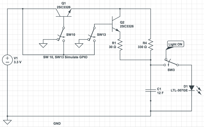
You should also protect the LED with a resistor. When the supercap C1 gets charged near 3.3V and you close (connect) SW3, all the current will go to the LED and could damage it.
The current of the supercap could also go back through the circuit to the MCU pins when they are low. Maybe you should place a diode to avoid that.
You could use two pins with resistors to charge the capacitor at different rates, but with diodes, to avoid the current going back to one of them. Also take into account that the voltage at C1 will not be constant, it will be increasing while charging.
The circuit is a bit of a simplification - the capacitor is actually a rechargeable coin cell battery and the LED sinks into a microcontroller where the input resistance should be about 50 ohms.
I’m worried about the voltage drop that could occur with a diode - ultimately impacting the charge level of the battery.
What are your thoughts about a low pass filter to convert the pwm to a stable voltage?
Ok, but the details of the battery and the MCU are important. Batteries have different voltages, overcharge/discharge problems, etc. Also your MCU (do you have one or two?) could have 3.3v or 5V in the pins.
Anyway, the problem with your schematic was the setup of the transistors, as they are in the high side they should be PNP instead of NPN, I think:
For NPN to be fulling conducting you need that Vbe > 0.7V. But as the battery gets charged it will be closer to 3.3V. So Vbe will be close to zero plus R4 drop, and the transistors will not be fully conducting, will have some resistance and voltage drop and eventually stop.
Otherwise with the transistor fully conducting the voltage drop should be around 0.1V or less.
The suggestion of using the MCU pin is good... except is the MCU being charged is the same than the one charging