Toggle Switch puzzle but sequential

I am trying to combine two different plans or at least modify one to accomplish a specific outcome. Let me set the stage:
Portable escape room box with various puzzles each "enabling" the next. I have everything working with a Keypad puzzle, a connect the proper wire puzzle and an RFID card placement puzzle. The last puzzle I am working on is a toggle switch puzzle. I have two ideas to combine. The first is a somewhat old video from Playful Technology (Toggle Switch Escape Room Puzzle Tutorial - YouTube) where he has a fairly simple toggle switch puzzle where a resettable switch pattern is programmed to the eeprom and a relay is activated (or deactivated) when the proper "On-Off" pattern in the eeprom is met. That is working flawlessly, but I want a bit more.

I want it so the switches have to be thrown sequentially in a pattern with some sort of feedback to let the solver know they are on the right path, but also have them need to reset the toggles to "off" if they are wrong.

The topic (which was closed long ago) on this forum "Detecting switches in order" (Detecting switches in order - #7 by alto777) seems to be what I want, but the code derived in that discussion is for pushbuttons and not the toggle switches I have and want.
These are the toggles from Amazon and I like them because they have a nice bright LED on when the switch is on and would like to keep them or something like them.

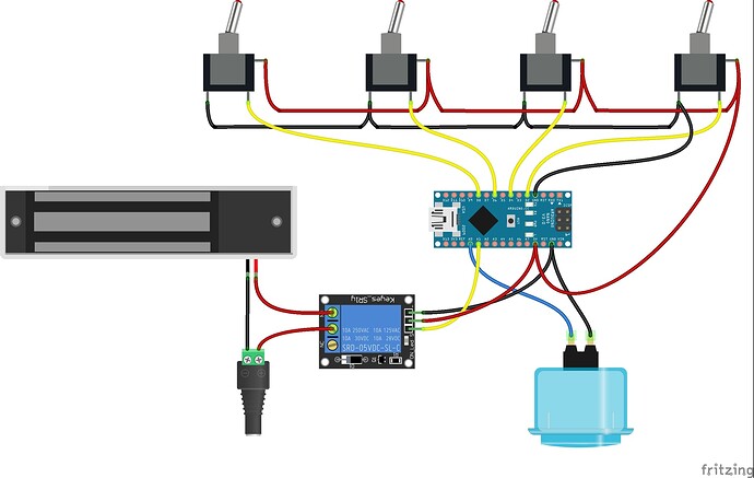
Basically, the way Playful Tech wired everything is spot on. each switch shares a ground, each switch shares a 5 volt, but each switch is tied individually to an Arduino input. In this way, the switches light up when turned on and complete a circuit to tell the Arduino it is on or off. Perfect.

When I try the other code, which is more advanced then what I know right now, when the switches are off, the led is dim and when they turn on the leds are brighter. Not a huge deal, but not preferred. I tried modifying the code and I think I get most of the way there, but it does not operate like the WOKWI simulation at all. in that example, when reset or powered on, the red and green leds alternate then sit in a ready state. when I try it with my toggle switches wired the way I have them it immediately goes into a wrong answer where the red led blinks.

Again, I know some code stuff, but I get a bit lost where to find the issue that makes this work.

In my scenario, I want these switches to act like progressively turning on parts of a machine and powering up the wrong parts sends it into an overload and they need to start again. I am thinking a series of green leds, 5 in this case, where it will light up another when one is correct and some red leds to clear the green leds currently on and flash themselves until reset. once the proper sequence is realized, open a relay and move on.

Can someone assist me here? Let me if you need more information and I will try my best to post it.
this would be easier to respond to if you posted your code.

TL;DR

Provide a short version.

Here is the code from Playful Tech that is working.

/**
 * "Toggle Switch State" puzzle 
 * 
 * This puzzle requires players to set a series of toggle switches to the correct on/off state. 
 * The solution can be set by pressing a "save" button, which stores the current state
 * of the switches to EEPROM, restored every time the puzzle is started.
 */

// Include the EEPROM library to enable us to save the pattern
#include <EEPROM.h>

// CONSTANTS
// The number of switches. Can be as many as you have digital pins available
const byte numSwitches = 5;
// The pins to which switches are connected
const byte switchPins[numSwitches] = { 2, 3, 4, 5, 6 };
// Pressing the button connected to this pin will save the current state to EEPROM
const byte savePin = A0;
// This pin will be driven LOW when the puzzle is solved
const byte relayPin = A1;
// Simple signature in first byte in EEPROM indicates stored data is valid
const byte eepromSignature = 121;

// GLOBALS
// An array to record the last known state of every switch
bool lastSwitchState[numSwitches];
// The current state of the puzzle
enum State { Initialising,
             Active,
             Solved };
State state = Initialising;
// The desired solution state - will be overwritten by value in EEPROM
bool solution[numSwitches] = { true, true, true, true, true };

// Set the puzzle solution to the current switch state and save to EEPROM
void savePattern() {
  // Erase the existing signature
  EEPROM.write(0, 0);
  // Store the current state of each switch to EEPROM
  for (int i = 0; i < numSwitches; i++) {
    solution[i] = lastSwitchState[i];
    EEPROM.write(i + 1, lastSwitchState[i]);
  }
  // Now write the signature back again to byte zero to show valid data
  EEPROM.write(0, eepromSignature);
  // Serial output
  Serial.println(F("Pattern saved to EEPROM"));
}

// Loads a saved switch pattern from EEPROM
void loadPattern() {
  // Check that the EEPROM starts with a valid signature
  if (EEPROM.read(0) == eepromSignature) {
    for (int i = 0; i < numSwitches; i++) {
      solution[i] = EEPROM.read(i + 1);
    }
    // Update the values of count and max delay
    Serial.println(F("Solution loaded from EEPROM"));
  } else {
    Serial.println(F("EEPROM data not valid"));
  }
}

void readState() {
  for (int i = 0; i < numSwitches; i++) {
    int switchValue = digitalRead(switchPins[i]);
    if (switchValue != lastSwitchState[i]) {
      Serial.print("Switch changed to");
      Serial.println(switchValue);
      lastSwitchState[i] = (bool)switchValue;
    }
  }
}

// Checks the last known state of switches against the solution
bool isPuzzleSolved() {
  // Assume the puzzle is solved
  bool solved = true;
  // Check each pin's state
  for (int i = 0; i < numSwitches; i++) {
    // If any switch fails to match its desired state
    if (lastSwitchState[i] != solution[i]) {
      //... then the puzzle has not been solved
      solved = false;
    }
  }
  return solved;
}

void setup() {
  // Initialise the input pins
  for (int i = 0; i < numSwitches; i++) {
    pinMode(switchPins[i], INPUT);
  }
  pinMode(savePin, INPUT_PULLUP);
  pinMode(relayPin, OUTPUT);

  // Start the serial connection
  Serial.begin(9600);
  Serial.println("Starting connection");

  // Load the saved solution from EEPROM
  loadPattern();

  // Set the puzzle state
  state = Active;
}

void loop() {
  // Get the current state of the switches
  readState();

  // Is the save button pressed?
  if (digitalRead(savePin) == LOW) {
    // Simple debounce
    while (digitalRead(savePin) == LOW) { delay(100); }
    // Save the current pattern to EEPROM
    savePattern();
  }

  // Is the puzzle solved?
  bool puzzleIsSolved = isPuzzleSolved();

  // If it's just been solved
  if (state == Active && puzzleIsSolved) {
    Serial.println(F("Puzzle has been solved!"));
    digitalWrite(relayPin, HIGH);
    state = Solved;
  }
  // If it was solved, but no longer is
  else if (state == Solved && !puzzleIsSolved) {
    Serial.println(F("Puzzle has been unsolved!"));
    digitalWrite(relayPin, LOW);
    state = Active;
  }
}

Here is the wiring diagram. I followed it but added a fifth switch.

presumably before rapid unplanned disassembly

so presumably the switches need to be thrown in sequence (e.g. left to right) and it is recognizes when a switch is thrown, if it needs to be and presumably the sequence is complete and successful is all the remaining switches in the sequence don't need to be thrown.

or should each toggle be toggled and either left OFF or moved one more time back to ON?

is the "savePin" really needed? wouldn't it be easier to program the code into the EEPROM thru the serial monitor? is there a use for an "capture" button that indicates when to compare the switch pattern to the pattern in EEPROM

1 Like

If I am able to move to the sequential solution, then, no, the whole eeprom setup would not be needed as I would dictate the solution in the program.

The switches would begin in an off state and the solution could indeed be modified so one is not needed but the result should be the same in practice. for simplicity sake, switch 1, switch 2, switch 3, switch 4 then switch 5. If any one switch is turned on out of order, then it goes into "fault" and resetting would be needed where all switches need to be turned off for a reset and another try

The other code I am trying to modify is below. I cannot seem to get it right, but that is what I am trying right now. I am in the middle of slicing and dicing this code, so I may have forgotten some things to remove, feel free to point out what I may have missed.

In all reality, I cannot even get this to see all the switches; IE In this program, the ready state is alternating blinking LEDS and a * *** Hi *** *message which happens, but then it goes directly into wrong answer mode where the red LED blinks. If I let the red blinking LED stop, I can throw some of the switches that send it back into "wrong" answer and the red LED blinks again (Pin 2, Pin3 and pin 5). Some switches don't appear to even be recognized (Pin4 and pin6). strange behavior from this code:

/* ************************************************************************
 
for arduino uno, mini, nano
10 keys (or toggle) to be activated in the right order

wiring :

pin  0 (RX reserved)  
pin  1 (TX reserved)
pin  2 -> toggle  2         // pin2-------1K resistor------toggle or key-------pin"Gnd"
pin  3 -> toggle  3         // pin3-------1K resistor------toggle or key-------pin"Gnd"
pin  4 -> toggle  4         // and so on 
pin  5 -> toggle  5         // toggle are named 2,3,4..11 as the pin number, for simplicity
pin  6 -> toggle  6 

pin A0 -> green Led        // pinA0-----1K resistor or less----- + led - -------pin"Gnd"
pin A1 -> red   Led        // pinA1-----1K resistor or less----- + led - -------pin"Gnd"

*/


 #define NbreToggle 10                                       // 

 word    PPImuSta ;                                          // reflète l'état instantané des touches
 word    PPImuMem;                                           //               (stockage intermédiaire)
 word    PPImuFro;                                           // reflète l'appui (front) d'une touche
 word    PPImuRel;                                           // reflète le relachement  d'une touche

 int     toggleProgress;                                     // 1,2,3,4...10   1,2,3,4..10  and so on

 word    blinkLedRed;
 word    blinkLedGreen;
 byte    imagePORTC = B00000001;

 unsigned long previousmillisKeys;                           // debounce timer
 unsigned long previousmillisLeds;                           // led duration timer 
 

 const word    TabReset [] = {                                                                // easy game,
                    0b0000000000000100,                      // expected pressure  1 =  pin2  // in the order,
                    0b0000000000001000,                      // expected pressure  2 =  pin3
                    0b0000000000010000,                      // expected pressure  3 =  pin4  // run once  
                    0b0000000000100000,                      // expected pressure  4 =  pin5  // before real game below  
                    0b0000000001000000,                      // expected pressure  5 =  pin6  

              };   //, *tab1;
                

const word    TabTwo [] = {                                                                   // real game,
                    0b0000000000100000,                      // expected pressure 1  =  pin5  // not in the order
                    0b0000000001000000,                      // expected pressure 2  =  pin6  
                    0b0000000000000100,                      // expected pressure 4  =  pin2
                    0b0000000000010000,                      // expected pressure 5  =  pin4   
                    0b0000000000001000,                      // expected pressure 9  =  pin3  
              };   //, *tab2;                
 
const word *tab;


void setup() {                                               // INITIALIZATION CODE 
  DDRC  |= B00000011;                                        // A0, A1 as output       (pinA0...pinA1) 
  PORTD |= B11111100;                                        // PC7..PC2 with pullups  (pin7....pin2)
  Serial.begin(9600);                                        // or 115200 (9600 is the default serial-monitor)
  Serial.println(" * *** Hi *** * ");                          // Hi
  blinkLedGreen = blinkLedRed = 8;                          // both Leds on reset
  tab = TabReset;                                            // at reset, game is: 1,2,3,4,5,6,7,8,9,10 (TabReset)
}


void loop() {                                                // MAIN CODE 
  SeeIfToggleOrKeysPressed();                                // pressure or change has been applied ?
  blinkLeds();                                               // Leds treatment
}  


                                                             // VARIOUS FUNCTIONS CODES
void SeeIfToggleOrKeysPressed(void) { //-------------------- // detection 1..16 keys :
  if (millis() - previousmillisKeys > 20) {                  // xx ms delay for debounce, usually 10 or 20 (ms)
    previousmillisKeys = millis();                           //
  
    word iii = ((~PIND & 0xFC) | ((~PINB & 0x0F) << 8));     // PORTD and B reading
    word jjj = PPImuSta;                                     // (debounce, rise, release and state detection)
    PPImuSta = iii & PPImuMem;                               // stable (subsiste pendant tout le temps de l'appui)
    PPImuMem = iii;                                          //                  (besoin interne, non exploitable)
    PPImuFro = (jjj ^ PPImuSta) & PPImuSta;                  // fugitif (front montant)   
    PPImuRel = (iii ^ jjj) & jjj;                            // fugitif : front descendant (relachement touche)  

    //-------------------------------------------------------// keys treatment :
    if (PPImuFro) OneInputPinJustChanged(PPImuFro);          // one key just pressed (or toggle just changed)
  }                                                          //
}                                                            //


void OneInputPinJustChanged(word Fro) { 
  toggleProgress++;                                          // increment counter, first or next expected pressure
  if (toggleProgress <= NbreToggle)  {                       // 
    if (PPImuFro == tab[toggleProgress-1]) blinkLedGreen = 20; // good choice for this one...
    else {blinkLedRed = 60; SetNewGame();}                   // error !
  } else SetNewGame();

  if (toggleProgress == NbreToggle) {                        //
    blinkLedGreen = blinkLedRed = 16;                        // MATCHED 10 KEYS !
    SetNewGame();                                            //
  }  
}


void blinkLeds(void) {      
  if (millis() - previousmillisLeds > 200) {                  // 
    previousmillisLeds = millis();   
  
    if (blinkLedGreen) blinkLedGreen--;
    if (blinkLedRed)   blinkLedRed--;    
  
    imagePORTC ^= B00000011;
    if (!blinkLedGreen) imagePORTC &= B11111110;                           // Green OFF
    if (!blinkLedRed)   imagePORTC &= B11111101;                           // Red OFF
    if (!blinkLedGreen && (toggleProgress > 0)) imagePORTC |= B00000001;   // leave Green Led ON when success in progress
    if (!blinkLedGreen && !blinkLedRed && !toggleProgress) imagePORTC &= B11111100;   // Green/Red OFF at NewGame
    PORTC = imagePORTC & B00000011;
  }
}    


void SetNewGame(void) {   
  tab = TabTwo;                                              // after 1st simple game at reset), the 2nd table is used
  toggleProgress = 0;                                        // come back to the begin
                                                             // (not here)  PORTC &= B11111100;
}

You are describing a state machine:

On thing that is unclear is what would be the expected behavior if the desired pattern was off-off-off-on-off?

That looks like what I am after. In the case of "correct" answer, a series of green LEDS should build. If an "Incorrect" answer is realized anywhere in the solving of the puzzle, it would flash some Red LEDS until all toggles are reset into an off position.

Almost seems like two different "state machines" if you will with two outcomes for two different solutions. One if correct with an outcome of green LEDS lit and the other with all toggles off resulting in a reset?

A little more tinkering and a bit more progress. I had the PORTD set to B111111100 and that set the pins to high, I wanted them low. Changed that and the LEDS act as they should on the switches (https://www.amazon.com/dp/B07VMDSW29?psc=1&ref=ppx_yo2ov_dt_b_product_details).

This code SHOULD go through a "test" of sorts that should have them all go through in order and then switch to the puzzle solution. It skips right over the "in order" section and flashes the red LED for the required "60" in the program and the solution works although backwards. By that I mean all the switches need to be on and then switched off to operate the puzzle sequence.

/* ************************************************************************
 
for arduino uno, mini, nano
10 keys (or toggle) to be activated in the right order

wiring :

pin  0 (RX reserved)  
pin  1 (TX reserved)
pin  2 -> toggle  2         // pin2-------1K resistor------toggle or key-------pin"Gnd"
pin  3 -> toggle  3         // pin3-------1K resistor------toggle or key-------pin"Gnd"
pin  4 -> toggle  4         // and so on 
pin  5 -> toggle  5         // toggle are named 2,3,4..11 as the pin number, for simplicity
pin  6 -> toggle  6 

pin A0 -> green Led        // pinA0-----1K resistor or less----- + led - -------pin"Gnd"
pin A1 -> red   Led        // pinA1-----1K resistor or less----- + led - -------pin"Gnd"

*/


 #define NbreToggle 5                                       // 

 word    PPImuSta ;                                          // reflète l'état instantané des touches
 word    PPImuMem;                                           //               (stockage intermédiaire)
 word    PPImuFro;                                           // reflète l'appui (front) d'une touche
 word    PPImuRel;                                           // reflète le relachement  d'une touche

 int     toggleProgress;                                     // 1,2,3,4...10   1,2,3,4..10  and so on

 word    blinkLedRed;
 word    blinkLedGreen;
 byte    imagePORTC = B00000001;

 unsigned long previousmillisKeys;                           // debounce timer
 unsigned long previousmillisLeds;                           // led duration timer 
 

 const word    TabReset [] = {                                                                // easy game,
                    0b0000000000000100,                      // expected pressure  1 =  pin2  // in the order,
                    0b0000000000001000,                      // expected pressure  2 =  pin3
                    0b0000000000010000,                      // expected pressure  3 =  pin4  // run once  
                    0b0000000000100000,                      // expected pressure  4 =  pin5  // before real game below  
                    0b0000000001000000,                      // expected pressure  5 =  pin6  

              };   //, *tab1;
                

const word    TabTwo [] = {                                                                   // real game,
                    0b0000000000100000,                      // expected pressure 1  =  pin5  // not in the order
                    0b0000000001000000,                      // expected pressure 2  =  pin6  
                    0b0000000000000100,                      // expected pressure 4  =  pin2
                    0b0000000000010000,                      // expected pressure 5  =  pin4   
                    0b0000000000001000,                      // expected pressure 9  =  pin3  
              };   //, *tab2;                
 
const word *tab;


void setup() {                                               // INITIALIZATION CODE 
  DDRC  |= B00000011;                                        // A0, A1 as output       (pinA0...pinA1) 
  PORTD |= B00000011111100;                                        // PC7..PC2 with pullups  (pin7....pin2)
  Serial.begin(9600);                                        // or 115200 (9600 is the default serial-monitor)
  Serial.println(" * *** Hi *** * ");                          // Hi
  blinkLedGreen = blinkLedRed = 8;                          // both Leds on reset
  tab = TabReset;                                            // at reset, game is: 1,2,3,4,5,6,7,8,9,10 (TabReset)
}


void loop() {                                                // MAIN CODE 
  SeeIfToggleOrKeysPressed();                                // pressure or change has been applied ?
  blinkLeds();                                               // Leds treatment
}  


                                                             // VARIOUS FUNCTIONS CODES
void SeeIfToggleOrKeysPressed(void) { //-------------------- // detection 1..16 keys :
  if (millis() - previousmillisKeys > 20) {                  // xx ms delay for debounce, usually 10 or 20 (ms)
    previousmillisKeys = millis();                           //
  
    word iii = ((~PIND & 0xFC) | ((~PINB & 0x0F) << 8));     // PORTD and B reading
    word jjj = PPImuSta;                                     // (debounce, rise, release and state detection)
    PPImuSta = iii & PPImuMem;                               // stable (subsiste pendant tout le temps de l'appui)
    PPImuMem = iii;                                          //                  (besoin interne, non exploitable)
    PPImuFro = (jjj ^ PPImuSta) & PPImuSta;                  // fugitif (front montant)   
    PPImuRel = (iii ^ jjj) & jjj;                            // fugitif : front descendant (relachement touche)  

    //-------------------------------------------------------// keys treatment :
    if (PPImuFro) OneInputPinJustChanged(PPImuFro);          // one key just pressed (or toggle just changed)
  }                                                          //
}                                                            //


void OneInputPinJustChanged(word Fro) { 
  toggleProgress++;                                          // increment counter, first or next expected pressure
  if (toggleProgress <= NbreToggle)  {                       // 
    if (PPImuFro == tab[toggleProgress-1]) blinkLedGreen = 20; // good choice for this one...
    else {blinkLedRed = 60; SetNewGame();}                   // error !
  } else SetNewGame();

  if (toggleProgress == NbreToggle) {                        //
    blinkLedGreen = blinkLedRed = 16;                        // MATCHED 10 KEYS !
    SetNewGame();                                            //
  }  
}


void blinkLeds(void) {      
  if (millis() - previousmillisLeds > 200) {                  // 
    previousmillisLeds = millis();   
  
    if (blinkLedGreen) blinkLedGreen--;
    if (blinkLedRed)   blinkLedRed--;    
  
    imagePORTC ^= B00000011;
    if (!blinkLedGreen) imagePORTC &= B11111110;                           // Green OFF
    if (!blinkLedRed)   imagePORTC &= B11111101;                           // Red OFF
    if (!blinkLedGreen && (toggleProgress > 0)) imagePORTC |= B00000001;   // leave Green Led ON when success in progress
    if (!blinkLedGreen && !blinkLedRed && !toggleProgress) imagePORTC &= B11111100;   // Green/Red OFF at NewGame
    PORTC = imagePORTC & B00000011;
  }
}    


void SetNewGame(void) {   
  tab = TabTwo;                                              // after 1st simple game at reset), the 2nd table is used
  toggleProgress = 0;                                        // come back to the begin
                                                             // (not here)  PORTC &= B11111100;
}

Here's something that might have been back around that thread you linked.

guess in correct order


Here's another version of the same thing.

another correct sequence program


They both use pushbuttons. I'm not in the lab right now, but I think it would be easy to make it use toggle switches that had to be closed one by one instraed.

Play with them first with the pushbuttons. If it seems like code you could use. I'll look into seeing about the toggle switches.

As I understand your words and diagram, the LEDs on the switches follow the switches without involving any code logic. If the LEDs on the toggles were under program control, I think a more lively device could be programmed. Just sayin' - the LED idea is clever and effective, and no doubt if switch tracking is all you want def saves on pins.

HTH

a7

I guess my question is that if you reset the switches to all off, (and the proper pattern is off-off-off-on-off), what happens next?

  • Does it immediately say "green green green red off"?

  • Do you push a button to check your progress so far?

  • Or are you checking that the 5 switches are all flipped on in a certain order. Such as with 5,2,1,3,4 being the target, a series of 5,2,1,4 would fault showing "green green off flashing-red green"?

"Guess in the correct order" seems like exactly what I want to accomplish. Works great with push buttons. I am going to look at what I have to change to make it 5 toggles and I have a bunch of the adafruit neopixel segment boards around. They are 8 pixels so I would like to see if calling out the first 5 pixels to build as it does right now and have the last three go red when wrong and then maybe amber while waiting the switches to be turned off or something in that realm.

I may be blind, but where is the answer dictated? I cannot seem to spot it.

I was looking for progress to be displayed as they went along

If the solution is indeed off-off-off-on-off, then if the player would turn on switch one, it would blink red and wait until all switches meet the "off" state then reset the puzzle. Once the player turns on switch four, and only switch four, the puzzle is solved and a relay kicks and a maglock opens or something celebratory like that.

But, yeah, in the initial "reset", all switches are off and the game cannot proceed until all are off. As the game proceeds and the player guesses correctly, an additional green LED would light up building on what was there already. Once a wrong guess is encountered, red LEDS would light, flash and continue flashing until all switches turn back off to reset the game.

I hope I am explaining myself correctly but the link above guess in correct order is almost exclusively what I am after, with the exception of toggle switches and some command to wait until all switches are off to reset.

I guess my puzzle will never have the answer of "ALL OFF" then.

Got something working I guess, not perfect yet and I am trying to figure out what needs adding. Here is where I am at after I modified a few things. Haven't added the LED to figure out it's code modification yet, but I'm getting there.

I can see now that the puzzle is random. I would need it to be more of a set answer more then anything. Would that be coming from here?

  for (int ii = 0; ii < 5000; ii++) {
    unsigned char tt = random(SEVEN);
    unsigned char ss = random(SEVEN);
    unsigned char temp;

Also, would I need to change every instance of "SEVEN"? it looks like that is used for LEDS as well, am I right? Also, re-introducing the toggles into the build instead of buttons works, except it still registers the switch off and not switch on. Plus, maybe some remnants of switching it to toggles rather then buttons makes it need to see the switch turned off and no other switch is recognized until the switch that was just made is turned off. Not sure where to find that though.

No, that is the whole point of using a constant identifier instead of a number "7". Somewhere you will find a definition of SEVEN, for example

const int SEVEN = 7;

or

#define SEVEN 7

But it's a lame effort, since if you change the value, it's still named 'SEVEN'. This is a bad sign for the expected quality of the program, I guess it saved me some time to bother reading it.

But, you could do two things to change it.

  1. Use a global search and replace edit and change SEVEN to NUMBER_OF_CHOICES or something that better explains what it is, and doesn't lock in a specific value
  2. Change the value of NUMBER_OF_CHOICES once on the line in which it is defined.

You should become familiar with this idea, because it is very important and is Programming 101. It is a simple example of data abstraction.

1 Like

Another example, if it can help : t1030673.ino - Wokwi Arduino and ESP32 Simulator

Yes. newCombo() makes a random combination starting by filling in 0..6, then 5000 times switching two.

It would be easy if I wasn't under the umbrella just now to make newCombo() instead just select and fill in the "next" preset combination from a list, as long as you need, of combinations.

SEVEN is just a way to not say 7 all over the place and I can't believe I am saying it now, but if I were to make it 6 big or 8, I would

# define SEVEN 8   // puzzle size, sorry Mom!

and let 'em wonder they who read my code.

I always put "sorry Mom!" after doing something so ridiculous… but you could global search and replace SEVEN, just don't use EIGHT, do something legit like PUZZLE_SIZE, 'K?

# define PUZZLE_SIZE  8

Still in no position to try fizing it for toggles. One thing I think you've realized (sry, looking through the tiny window here) is that toggles, the ones I can afford anyway, have no way to be placed in one position or another under program control. So there's the problem of resetting involving human action.

I'll be able to give this better attention when I am back in the lab.

a7

Looks like the same variation, but with the answer declared, which I like. Still would need to address the buttons to switches I guess. Plus, the other had the feedback pixels letting the user know where they stand towards the answer. Thanks