I'm using a 7 inch resistive touch screen which has an SSD1963 controller running 8080 mode in 16 bit parallel off a Teensey 4.1. It's running at 60hz with full screen refreshes of a memory buffer and I've tied into the TE sync line. Running it in portrait at 800 tall x 480 wide.
The issue is with the touch screen values. The raw values come in via SPI. However they are not linear along each axis. The raw values are as follows
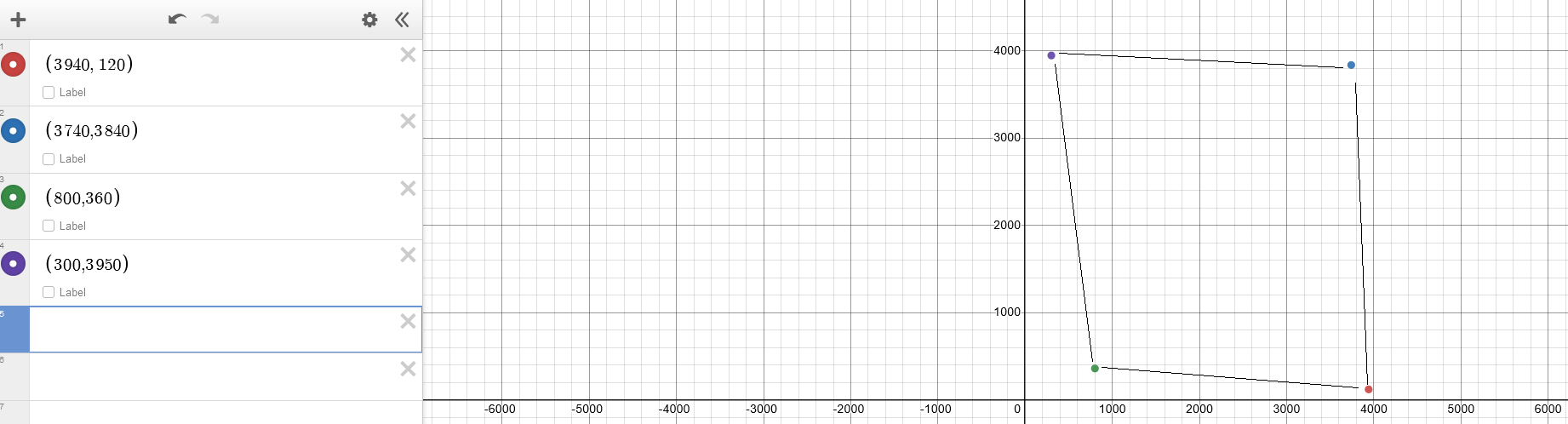
X Positions
Top left = 3940
Bottom Left = 3740
Top Right = 800
Bottom Right = 330
X Positions (edit this is y position)
Top left = 120
Top Right = 360
Bottom Left = 3840
Bottom Right = 3950
It's almost like a parallelogram, however the difference between the top right and top left X positions are way more than the other axis, which is making it almost impossible to map accurate touches.
Any ideas on how to map these non linear values for accurate touch positions?
Yes the writing to the screen is correct. Im pretty happy with the setup code for the screen. Thats all running on 16 bit parallel.
The touchscreen chip is seperate to the driver chip an XP2046. The touch screen data comes through seperate SPI pins. Im using the XP2046 library for the touch.
Im guessing the touch part of the screen on the display wasnt placed properly? I am getting values in each corner, and the Z raw values seem correct.
Thats an interesting idea, i will try that tonight.
Your graphing diagram puts it into perspective. I feel like we need to run the mapping twice. First to get how far down the y coordinate we are, as that will affect the x coordinate.
The OP's problem uses an extra couple degrees of freedom beyond non-orthogonal--If it was just non-orthogonal, the 4 corner points would make a rhombus.
That is can be solved by adding an offset vector and using a nonunitary transformation matrix, which gives you six or more parameters to determine. Matching four or more sets of points by least squares analysis is the usual approach to determine those parameters.
The other approach, which is far simpler, will work much better, and the one I strongly recommend, is to buy a touchscreen that functions correctly.
That's much less simple than the oblique transformation at the #11 link. I think you need to fit a full 8 parameters, and with 4 points you have 8 degrees of freedom -- it should solve out exactly without least squares.
Yes, a non-broken touchscreen would be much better.
Something has to be shorting out the resistances in the screen to make it act non-linear, and there are no guarantees that the defect will be stable, or that the values for points inside of the corners change consistently.
Interesting. Lowering the SPI clock from 1mhz to 0.5mhz closes the gap on the left side X values.
Top stays 3900, bottom goes to 3800 (was 3700) Right side values stay the same
Increasing the SPI clock to 2mhz makes it worse.
Grounding issue? Noise?
Im reading the values 60 times a second. I'm also taking an average of 5 SPI reads at a time