I posted about this at the end of another thread, but wanted to provide a bit more information, and give it its own thread.
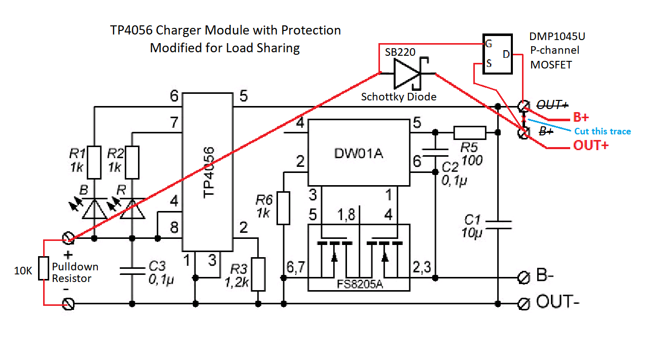
This is a modification of the standard TP4056 charger module - the one with battery protection built in - to add the three components that make up a load sharing circuit - a logic level P-channel mosfet, a schottky diode, and a resistor. The OUT+ and B+ terminals of the module are shorted together, but if we cut that trace, and reverse the functions of those terminals, we can add the three parts directly to the module. The module and the schematic showing the modification are shown in the pictures below.
In addition to the three parts, you will also need a little adapter board for mounting the SOT-23 package of the mosfet so it can be connected into the circuit. These are called "SOT-23 to DIP" adapters, or possibly "SOT-23 to SIP". Or if you still have any NDP6020P mosfets in a TO-220 package, you won't need the adapter. Unfortunately, the NDP6020P has been discontinued, and I don't know of another suitable logic level P-channel mosfet in a through-hole package.
The terminal holes on the board are not big enough to hold the multiple wires connected to them, but the pads are pretty big, and you can also solder to the pads on the bottom of the board.
Keep in mind the following:
The charging current is set at 1A by default. Your battery has to be able to tolerate that, or you can change the 1.2K R3 resistor to a higher value as set forth in the datasheet.
Your mains 5V supply must be able to deliver both the 1A charging current plus the load current at the same time.
This circuit does not work with solar panels. It depends on the mains voltage being either 5V or 0V, but not in between.
Downstream of this circuit you will need a regulator of some kind - either a 3.3V LDO or buck converter, or a 5V boost converter. You should also have a manual on/off switch before the regulator so you can prevent the regulator from wasting power when the device is not in use, but still be able to charge the battery if needed when the device is switched off.
If your battery is already protected, you can avoid double protection by bridging the B- and OUT- terminals, and removing R5 (or cutting its trace). The module comes in a version with no protection built in, but it may be physically more difficult to do the modification on that version since it only has B+ and B- output terminals.
No, the mosfet orientation is not incorrect. The drain goes to the battery, and the source to the load. That's so the body diode will block high voltage from coming back into the battery.
It is still a mystery to me why the module makers of the Far East don't offer a TP4056 module with load sharing built in. They would have better luck than us finding mosfets these days.
I know of one which uses the MCP73871, which has load sharing inside the chip. But it doesn't have a USB connector, requires a giant 4700uF cap, and can only charge at 500mA. If you know of another module that combines charging with load sharing, I'd like to know about it. There is a J5019 module that combines the TP4056 and the MT3806 boost converter, but has no load sharing.
No, that's the J5019 module I referred to in #3. I actually have one of them. It has the TP4056 charger, but no protection, and it has the MT3608 adjustable boost converter. But it has no load sharing circuit. Here's my video on load sharing for a different product, and why it may be needed:
Hi, I'm not an expert, could you help me understand this?
Would a schottky diode, in place of the MOSFET, be enough to block high voltage from coming back into the battery? And therefore the following would work:
When the USB 5v supply is connected D1 will be forward bias and power the boost converter but D2 will be reverse bias, therefor no current will be drawn from Out+ and the battery will be isolated so the charger can charge it.
When the USB 5v supply is not connected D2 will reverse bias and prevent any current flowing back. D1 will be forward bias and allow the battery to power the boost converter.
Am I missing something? What's the advantage of the MOSFET? Especially in this orientation.
Two diodes will certainly work fine. But the diodes will have a voltage drop of about 0.3V. So a diode in the battery line will reduce battery life. The whole point of using the mosfet is to eliminate that voltage drop, and thereby maximize battery life. But if that's not an issue, then two diodes is certainly the simpler solution.
If the mosfet is turned off, its body diode acts like a plain diode would act - it blocks high voltage from coming back into the battery. But when the mosfet is turned on, the body diode is bypassed, and there's a near-perfect path from the battery to the load, with almost no voltage drop.
I was watching a video from Andreas Spiess, and you can see him testing a fake NDP6020P from aliexpress. https://youtu.be/s7ABp4OWy7U?t=225. He records VT as 0.82V. I believe vt is the same as vgs(th) (gate threshold voltage), so at 0.82v it is definitely a logic level mosfet.
Andreas' video is wrong, and I am right. I have demontrated in both simulation and a physical circuit that under moderate solar illumination his circuit results in battery current flowing through the mosfet's body diode - because the mosfet is off - with a resulting 0.7V drop, which is not what you want.
I have a Github repo that goes into this in considerable detail. The final working version for solar is in the folder "Opamp Version Revisited".
I find your solar charger project very interesting. I have a question about it. Is there a particular reason why you used an opamp and not a comparator?
Many comparators have an open drain output that would have required a pullup resistor, which would waste battery current. So I wanted a push/pull output. And I wanted the common mode input to exceed the positive rail. I'm sure there are comparators that have these characteristics, but I found the opamp early on, and didn't look further. I should say that I am not an engineer, so my choice may not be the best one. But the opamp was available in a DIP package, in stock, and cheap, and it worked.
Note that I updated the Github repo a few days ago with a new version of the circuit. It gets more complicated every time I fix a problem, so I'm very open to any other design someone might have. It just has to be hobbyist friendly - none of this QFN rubbish.
I am also only a hobbyist and have only limited knowledge about OpAmps and Comparators.
That is why I asked. Since two voltages are compared and at least in your first version no amplification is used, I just wondered if a comparator is not better suited. Something like the LMC7211, for example.
But thanks for your answer. Your arguments are very understandable.