Hello,
I'm designing a PCB using KiCad and I would like to incorporate a battery charger module on it. Until now, I was using the TP4056 by soldering this small PCB module onto my PCB card (6 holes for the inputs / output). And of course I would like to skip this part.
What would be the easiest way (without this USB plug)? I would like just the input for the solar panel (JST connector) and the outputs (battery and circuit). I found some on the web but they all have this USB plug and they are all making a separate module.
As you can guess, I’m not expert.
Thanks a lot for your help.
Laurent
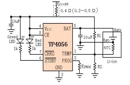
The TP4056 datasheet has a typical application circuit, just follow that and use whatever connectors you choose.
Of course run up the chosen circuit on a breadboard so that you can be sure the actual circuit works, before commiting it to a PCB design.
Thanks for your reply.
Are you talking about this?
Actually, I watched the video from this guy on YouTube and he explains pretty well.

If you go to 25:25, do you think I could simply switch the input from the USB to a JST plug that I will plug to a solar panel?
If you are not including any battery protection circuits, such as the DW01, then you only have one output, which is for both battery and load. You would then need to use protected batteries.
Also remember that the TP4056 has a maximum input voltage, so your panel should be no higher than that when open circuit.
After reading more about the different options for the TP4056, I understand more how it works and I think I will make my life easy and solder the module with the battery protection on my PCB.
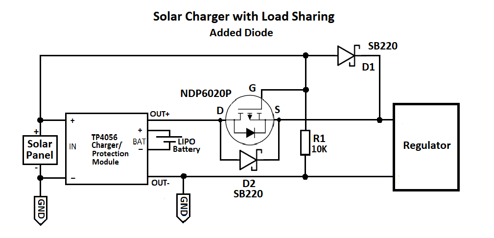
Btw, I found this (https://www.instructables.com/Load-Sharing-Use-Solar-Panel-Safely-With-TP4056/). Do you think this is something I should do in my circuits? :

Thanks a lot for your help
That load sharing circuit works when the input power is 5V USB power. But he's wrong about using it with a solar panel. In low light, the panel will produce some small amout of current, but the panel voltage will rise to the level of the battery voltage. That will raise the gate voltage and turn off the mosfet when the battery is needed to provide most of the load current. As a result, the battery current will flow through the mosfet's body diode, with a resulting 0.7V drop. So at the very worst time, when the battery has been working all night and is mostly discharged, when the light comes up even a little bit, the voltage will drop by 0.7V, and that may shut down your circuit.
I have a Github repo devoted entirely to this problem, and if you have nothing else to do you are welcome to read it.
https://github.com/gbhug5a/Solar-Power-Load-Sharing
The load sharing circuit for use with a solar panel is more complicated, and includes an opamp. But are you sure you need load sharing? If you can put your circuit to sleep periodically, charging termination may still take place properly, and a load sharing circuit wouldn't be absolutely necessary. Can you tell us more about your project?
Edit: I should have said that another option is to use his load sharing circuit, but add a schottky diode across the mosfet. You still have a voltage drop in low light, but a smaller one - more like 0.3V. But that drop will rise as load current increases, so that's not a great solution.
Thanks a lot @ShermanP for sharing that and explaining his circuit.
My circuit has an ESP32 that will transfer data of different sensors (potentiometer / temperature, rain gauge / temperature, inclinometer...) through LoRa. I used to transmit data through WiFi but it uses too much current. Plus, I'm working with ESP32 modules, but trying to work with bare ESP32 to have a low consumption during deepsleep. So you're probably right about the need of a load sharing.
I'm working on the design of the circuit now. I'm not expert and hope I'm not doing anything wrong ![]() I just wanted to keep this option in my circuit in case I need it in future.
I just wanted to keep this option in my circuit in case I need it in future.
This project is powered with a 18650 battery. I don't like it. Too big. I would prefer SAFT batteries but I was told these battery are good when current stays low but they don't like when there are peaks of current. When ESP wakes up and send data, it goes to 30-50mA for 1-2 sec.
Anyway, that's another topic but this is basically my project.
Thanks again
It sounds like your circuit will sleep most of the time, assuming you can also shut down your sensors and radio during the sleep period. If that's the case, I don't think the load sharing circuit is needed. The only downside of not having one is that when your 18650 has been fully charged, the charger will shut down until battery voltage drops to 4.1V. So the battery will cycle between 4.2V and 4.1V even in bright sun.
One thing to think about is that lithium ion batteries don't like to be charged when the temperature is below freezing. I don't know of a good way to deal with that.
Indeed, no charging below zero.
Lots of electronic solutions of course, but for simplicity I wonder if there is a simple thermostat that turns off at 0C ?
I wonder if something on this Aliexpress listing would work. Maybe 0C normally open.
https://www.aliexpress.us/item/2251832183121287.html
Maybe there's something even simpler.
They are very rarely in freezing conditions. If it is, it will be during the night, so no charging.
Anyway, I might be wrong but I don't really like these 18650. Too big. If I go to low power, do you have any other suggestions? I will jump from 30uA (deepsleep) to 30mA (during 1-2 sec so data can be sent by LoRa or maybe WiFi) every 2 hours.
What happens to all your sensors, and the radio, when the ESP is sleeping? Are they powered down too? Is that 30uA the entire circuit, or just the ESP?
You might look at lithium polymer batteries. The TP4056 charges them too. They are rectangular, but flat. Search on Amazon for "lithium polymer batteries" to see what's available.
Yes, I will turn them off and put the LoRa to sleep.
Actually, this is in theory ![]() It's what I except it to be. I will receive my final circuit in 2-3 weeks
It's what I except it to be. I will receive my final circuit in 2-3 weeks ![]()
Yes, I had a look at them before but I wasn't sure if they would behave better than the 18650. I have one. I will test it definitely. Thanks a lot @ShermanP
I always test low deep sleep stuff on a breadboard, before waiting for a PCB (the final circuit ?)
It can be very difficult, close to impossible, to debug high sleep currents and find solutions, on a finished PCB. Easy peasy on a breadboard.
What do you mean, haven't you breadboarded or protoboarded your project first?
It will probably not be your "final circuit".
Get your hardware out and build the thing and make sure it all works, experiment!!!!!!
What are you waiting for?
Tom.. ![]()
![]()
![]()
![]()
![]()
![]()
![]()
Of course! I already did. But with the ESP32 NodeMCU and the Mini ESP32. I just never did it with the bare ESP32 alone. I wish I could but I don't have the material to solder such a small microcontroller.
I just added 1 or 2 things but I will show you (or in another topic) to make sure I did every correctly ![]()
Easy enough, you just need some thin enamel coated copper wire. Attach one end of the wire to the ESP32 pin and wrap the other around a 0.1" pin. Plug the finished assembly into a breadboard. There is even a wire designed for wire wrap that you dont need to remove the insulation, it self fluxes when melted with solder.
But you have to want to do it ..........
Yeah, I just need... ![]()
Actually, you gave me an idea. I will order my own ESP32 soldered on a small board with the BOOT and RESET button and the connection to load the program (I have the USB to UART TTL plug). That will help me for future projects
All the lithium polymer cells I've seen have protection built in. So you could use the TP4056 module without protection.
