Traffic Light with LCD in which time left for signal will be shown

Hello!
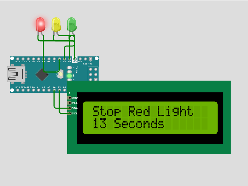
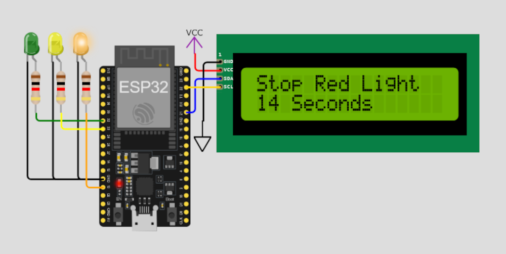
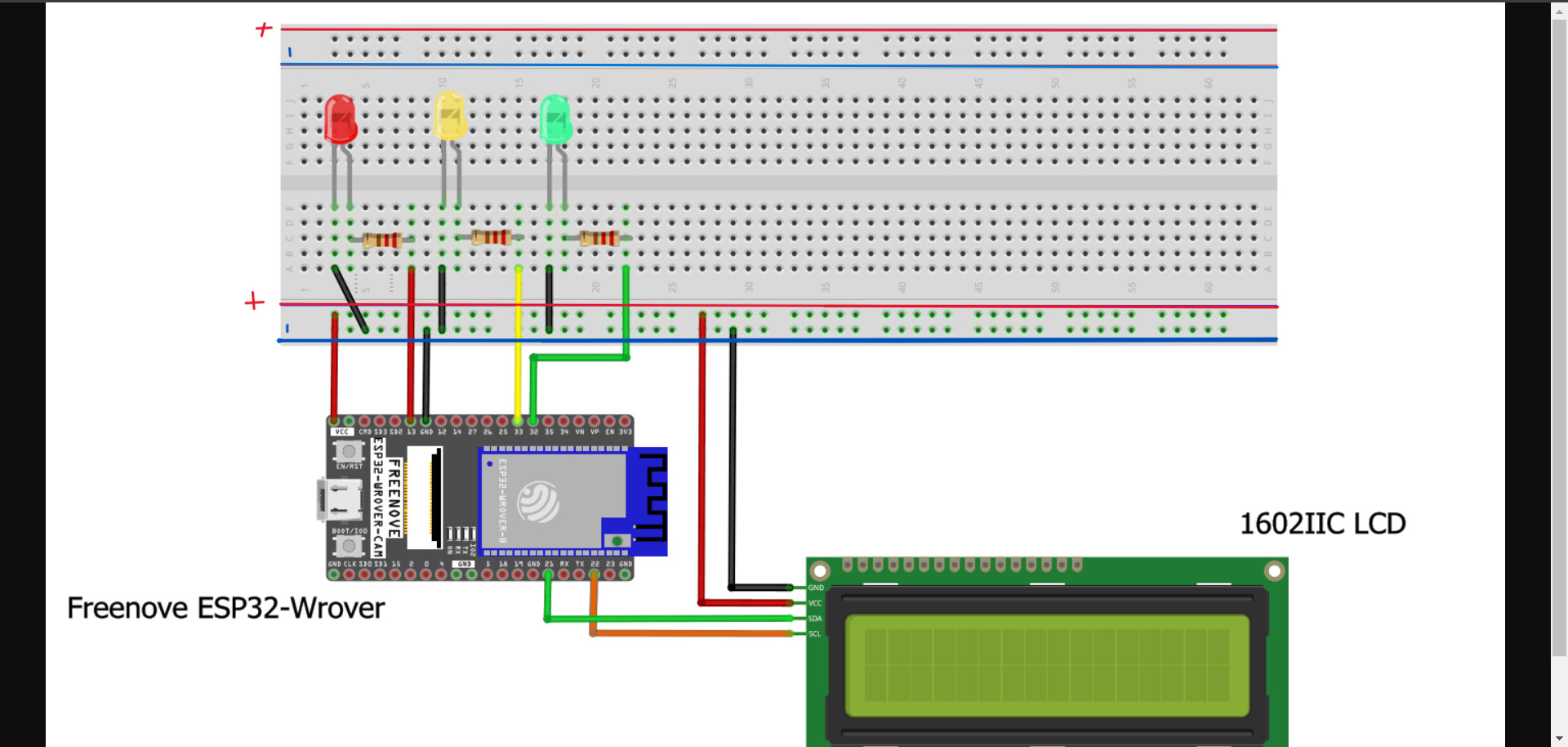
I want to build a Traffic Light with LCD in which time left for signal will be shown. I manage to make the wiring (see the diagram) and also I build the code.

#include <Wire.h>
#include <LiquidCrystal_I2C.h>

#define SDA_PIN 21
#define SCL_PIN 22

int red = 13;
int yellow = 33;
int green = 32;

LiquidCrystal_I2C lcd(0x27, 16, 2);

void setup() {
  Wire.begin(SDA_PIN, SCL_PIN);
  
  pinMode(red, OUTPUT);
  pinMode(yellow, OUTPUT);
  pinMode(green, OUTPUT);

  lcd.init();
  lcd.backlight();
  lcd.setCursor(0, 0);
  lcd.print("Turning On");
  lcd.setCursor(0, 1);
  lcd.print("Traffic Light");
  delay(2000);
  lcd.clear();

  lcd.setCursor(0, 0);
  lcd.print("SYSTEM");
  lcd.setCursor(0, 1);
  lcd.print("ON");
  delay(1500);
  lcd.clear();  
}

void loop() {
  // Red light
  displayLight("Stop Red Light", 15, red);
  
  // Yellow light
  displayBlinkingLight("On Yellow Light", 5, yellow);
  
  // Green light
  displayLight("GoGo Green Light", 20, green);
  
  // Yellow light again
  displayBlinkingLight("Of Yellow Light", 5, yellow);
}

void displayLight(const char* message, int seconds, int pin) {
  lcd.clear();
  lcd.setCursor(0, 0);
  lcd.print(message);
  
  for (int i = seconds; i > 0; i--) {
    lcd.setCursor(0, 1);
    if (i > 1) {
      lcd.print(i);
      lcd.print(" Seconds");
    } else {
      lcd.print(i);
      lcd.print(" Second");
    }
    digitalWrite(pin, HIGH);
    delay(1000);
  }
  
  digitalWrite(pin, LOW);
}

void displayBlinkingLight(const char* message, int seconds, int pin) {
  lcd.clear();
  lcd.setCursor(0, 0);
  lcd.print(message);
  
  for (int i = seconds; i > 0; i--) {
    lcd.setCursor(0, 1);
    if (i > 1) {
      lcd.print(i);
      lcd.print(" Seconds");
    } else {
      lcd.print(i);
      lcd.print(" Second");
    }
    digitalWrite(pin, HIGH);
    delay(500);
    digitalWrite(pin, LOW);
    delay(500);
  }
}

My issue is that when I'm running it, the text is print it on my LCD but the lights are off completely. Do you have any idea what could be the problem with my lights that are not on?

#include <LiquidCrystal_I2C.h>

int red = 4;
int yellow = 3;
int green = 2;

LiquidCrystal_I2C lcd(0x27, 16, 2);

void setup() {
  pinMode(red, OUTPUT);
  pinMode(yellow, OUTPUT);
  pinMode(green, OUTPUT);

  lcd.init();
  lcd.backlight();
  lcd.setCursor(0, 0);
  lcd.print("Turning On");
  lcd.setCursor(0, 1);
  lcd.print("Traffic Light");
  delay(2000);
  lcd.clear();

  lcd.setCursor(0, 0);
  lcd.print("SYSTEM BOOTING");
  lcd.setCursor(0, 1);
  for (int i = 0; i < 16; i++) {
    delay(1000);
    lcd.print("*");
  }
  delay(1000);
  lcd.clear();
}

void loop() {
  // Red light
  displayLight("Stop Red Light", 15, red);

  // Yellow light
  displayBlinkingLight("On Yellow Light", 5, yellow);

  // Green light
  displayLight("GoGo Green Light", 20, green);

  // Yellow light again
  displayBlinkingLight("Of Yellow Light", 5, yellow);
}

void displayLight(const char* message, int seconds, int pin) {
  lcd.clear();
  lcd.setCursor(0, 0);
  lcd.print(message);

  for (int i = seconds; i > 0; i--) {
    lcd.setCursor(0, 1);
    if (i > 1) {
      lcd.print(i);
      lcd.print(" Seconds");
    } else {
      lcd.print(i);
      lcd.print(" Second");
    }
    digitalWrite(pin, HIGH);
    delay(1000);
  }

  digitalWrite(pin, LOW);
}

void displayBlinkingLight(const char* message, int seconds, int pin) {
  lcd.clear();
  lcd.setCursor(0, 0);
  lcd.print(message);

  for (int i = seconds; i > 0; i--) {
    lcd.setCursor(0, 1);
    if (i > 1) {
      lcd.print(i);
      lcd.print(" Seconds");
    } else {
      lcd.print(i);
      lcd.print(" Second");
    }
    digitalWrite(pin, HIGH);
    delay(500);
    digitalWrite(pin, LOW);
    delay(500);
  }
}

Your code works! Verify your LED wiring (Anode toward Signal, Cathode toward Ground)

diagram.json for wokwi
{
  "version": 1,
  "author": "Anonymous maker",
  "editor": "wokwi",
  "parts": [
    { "type": "board-esp32-devkit-c-v4", "id": "esp", "top": 0, "left": -14.36, "attrs": {} },
    {
      "type": "wokwi-lcd1602",
      "id": "lcd1",
      "top": -12.8,
      "left": 120.8,
      "attrs": { "pins": "i2c" }
    },
    {
      "type": "wokwi-led",
      "id": "led2",
      "top": -22.8,
      "left": -111.4,
      "attrs": { "color": "green" }
    },
    {
      "type": "wokwi-resistor",
      "id": "r2",
      "top": 43.2,
      "left": -115.75,
      "rotate": 90,
      "attrs": { "value": "1000" }
    },
    {
      "type": "wokwi-led",
      "id": "led3",
      "top": -22.8,
      "left": -82.6,
      "attrs": { "color": "yellow" }
    },
    {
      "type": "wokwi-resistor",
      "id": "r3",
      "top": 43.2,
      "left": -86.95,
      "rotate": 90,
      "attrs": { "value": "1000" }
    },
    {
      "type": "wokwi-led",
      "id": "led4",
      "top": -22.8,
      "left": -53.8,
      "attrs": { "color": "orange" }
    },
    {
      "type": "wokwi-resistor",
      "id": "r4",
      "top": 43.2,
      "left": -58.15,
      "rotate": 90,
      "attrs": { "value": "1000" }
    },
    { "type": "wokwi-vcc", "id": "vcc1", "top": -18.44, "left": 86.4, "attrs": {} },
    { "type": "wokwi-gnd", "id": "gnd1", "top": 86.4, "left": 95.4, "attrs": {} }
  ],
  "connections": [
    [ "esp:TX", "$serialMonitor:RX", "", [] ],
    [ "esp:RX", "$serialMonitor:TX", "", [] ],
    [ "led2:A", "r2:1", "green", [ "v0" ] ],
    [ "led3:A", "r3:1", "green", [ "v0" ] ],
    [ "led4:A", "r4:1", "green", [ "v0" ] ],
    [ "esp:GND.1", "led2:C", "black", [ "h0" ] ],
    [ "esp:GND.1", "led3:C", "black", [ "h-57.45", "v-134.4" ] ],
    [ "esp:GND.1", "led4:C", "black", [ "h-28.65", "v-134.4" ] ],
    [ "esp:32", "r2:2", "green", [ "h-76.65", "v-8.4" ] ],
    [ "esp:33", "r3:2", "yellow", [ "h-47.85", "v-18" ] ],
    [ "esp:13", "r4:2", "orange", [ "h-19.05", "v-85.2" ] ],
    [ "vcc1:VCC", "lcd1:VCC", "red", [ "v0" ] ],
    [ "gnd1:GND", "lcd1:GND", "black", [ "v0" ] ],
    [ "lcd1:SDA", "esp:21", "blue", [ "h-28.8", "v38.6" ] ],
    [ "lcd1:SCL", "esp:22", "gold", [ "h-9.6", "v19.5" ] ]
  ],
  "dependencies": {}
}
1 Like

Sorry I cannot follow your picture, the wires connections are not defined.

Please, show a photograph of your project.

Indeed my LED wiring was wrong! Now it works fine! Thank you for suggestion!

The second is better but they do not show the LED orientation. I use SMD and they do not look like this and the resistor labels are missing Some users are color blind. .

This topic was automatically closed 180 days after the last reply. New replies are no longer allowed.