I'm new to Arduino and I have some issues building a Traffic Light with LCD.
I'm trying to adjust the following code, but I get the error" compilation error: no matching function for call to: LiquidCrystal::LiquidCrystal(int, int) ". Can you give me some direction how to resolve this error?
wrong lib, or wrong lcd. you attached I2C lcd it need other lib.
and for chosen lib this:
is incorrect, what error message say already.
correct one is:
LiquidCrystal lcd(21, 22, 23, 24, 25, 26);
Could it be the #include for the same file in there twice?
You need the LiquidCrystal_I2C library. Also, ONLY include a library once.
Like this
#include <LiquidCrystal_I2C.h>

LiquidCrystal_I2C lcdDisplay(0x27, 16, 2);
The SDA/SCL wires go to esp32 default pins 21 and 22, no need to provide i code if using defaults.

1 Like
in real life, not in simulators, sometimes, is need to adjust I2C address, most frequent are 0x27 and 0x3F.
I have never encountered a 1602 having other than 0x27 but YMMV.
@cristian_m100 you should really learn for() loop function
Thank you for help! I followed your instruction and now I have no error, but the issue is now that on the LCD doesn't display any message(the LCD is on, but no message). Also, the led's are blinking but not according to code! Do you have any idea what could be the problem?
#include <LiquidCrystal_I2C.h>
int red = 13;
int yellow = 33;
int green = 32;
LiquidCrystal_I2C lcd(0x27, 16, 2);
void setup(){
pinMode(red, OUTPUT);
pinMode(yellow, OUTPUT);
pinMode(green, OUTPUT);
lcd.begin(16, 2);
lcd.setCursor(0, 0);
lcd.print("Turning On");
lcd.setCursor(0, 1);
lcd.print("Traffic Light");
delay(2000);
lcd.clear();
lcd.setCursor(0, 0);
lcd.print("SYSTEM");
lcd.setCursor(0, 1);
lcd.print("ON");
delay(1500);
lcd.clear();
}
void loop(){
lcd.begin(16, 2);
lcd.setCursor(0, 0);
lcd.print("Stop Red Light");
    lcd.setCursor(0, 1);
    lcd.print("15 Second");
  digitalWrite(red,  HIGH);
    delay(1000);

  lcd.setCursor(0, 1);
    lcd.print("14 Second");
  digitalWrite(red, HIGH);
    delay(1000);
  lcd.setCursor(0, 1);
    lcd.print("13  Second");
  digitalWrite(red, HIGH);
    delay(1000);

  lcd.setCursor(0,  1);
    lcd.print("12 Second");
  digitalWrite(red, HIGH);
    delay(1000);
    lcd.setCursor(0, 1);
    lcd.print("11 Sec");
  digitalWrite(red, HIGH);
    delay(1000);
     lcd.setCursor(0, 1);
    lcd.print("10 Sec");
  digitalWrite(red, HIGH);
    delay(1000);
     lcd.setCursor(0, 1);
    lcd.print("09 Sec");
  digitalWrite(red, HIGH);
    delay(1000);
  lcd.setCursor(0, 1);
    lcd.print("08 Second");
  digitalWrite(red,  HIGH);
    delay(1000);
  lcd.setCursor(0, 1);
    lcd.print("07 Second");
  digitalWrite(red, HIGH);
    delay(1000);
  lcd.setCursor(0, 1);
    lcd.print("06  Second");
  digitalWrite(red, HIGH);
    delay(1000);
  lcd.setCursor(0,  1);
    lcd.print("05 Second");
  digitalWrite(red, HIGH);
    delay(1000);
  lcd.setCursor(0,  1);
    lcd.print("04 Second");
  digitalWrite(red, HIGH);
    delay(1000);
  lcd.setCursor(0,  1);
    lcd.print("03 Second");
  digitalWrite(red, HIGH);
    delay(1000);
    lcd.setCursor(0, 1);
    lcd.print("02 Second");
  digitalWrite(red,  HIGH);
    delay(1000);
  lcd.setCursor(0, 1);
    lcd.print("01 Second");
  digitalWrite(red, HIGH);
    delay(1000);
  lcd.clear();
digitalWrite(red, LOW);
lcd.setCursor(0, 0);
lcd.print("On Yellow Light");
lcd.setCursor(0, 1);
lcd.print("05 Second");
digitalWrite(yellow, HIGH);
delay(1000);
digitalWrite(yellow, LOW);
delay(500);
lcd.setCursor(0, 1);
lcd.print("04 Second");
digitalWrite(yellow, HIGH);
delay(1000);
digitalWrite(yellow, LOW);
delay(500);
lcd.setCursor(0, 1);
lcd.print("03 Second");
digitalWrite(yellow, HIGH);
delay(1000);
digitalWrite(yellow, LOW);
delay(500);
lcd.setCursor(0, 1);
lcd.print("02 Second");
digitalWrite(yellow, HIGH);
delay(1000);
digitalWrite(yellow, LOW);
delay(500);
lcd.setCursor(0, 1);
lcd.print("01 Second");
digitalWrite(yellow, HIGH);
delay(1000);
digitalWrite(yellow, LOW);
delay(500);
lcd.setCursor(0, 1);
lcd.print("01 Second");
lcd.setCursor(0, 0);
lcd.print("GoGo Green Light");
lcd.setCursor(0, 1);
lcd.print("20 Second");
digitalWrite(green, HIGH);
delay(1000);
lcd.setCursor(0, 1);
lcd.print("19 Second");
digitalWrite(green, HIGH);
delay(1000);
lcd.setCursor(0, 1);
lcd.print("18 Second");
digitalWrite(green, HIGH);
delay(1000);
lcd.setCursor(0, 1);
lcd.print("17 Second");
digitalWrite(green, HIGH);
delay(1000);
lcd.setCursor(0, 1);
lcd.print("16 Second");
digitalWrite(green, HIGH);
delay(1000);
lcd.setCursor(0, 1);
lcd.print("15 Second");
digitalWrite(green, HIGH);
delay(1000);
lcd.setCursor(0, 1);
lcd.print("14 Second");
digitalWrite(green, HIGH);
delay(1000);
lcd.setCursor(0, 1);
lcd.print("13 Second");
digitalWrite(green, HIGH);
delay(1000);
lcd.setCursor(0, 1);
lcd.print("12 Second");
digitalWrite(green, HIGH);
delay(1000);
lcd.setCursor(0, 1);
lcd.print("11 Sec");
digitalWrite(green, HIGH);
delay(1000);
lcd.setCursor(0, 1);
lcd.print("10 Sec");
digitalWrite(green, HIGH);
delay(1000);
lcd.setCursor(0, 1);
lcd.print("09 Sec");
digitalWrite(green, HIGH);
delay(1000);
lcd.setCursor(0, 1);
lcd.print("08 Second");
digitalWrite(green, HIGH);
delay(1000);
lcd.setCursor(0, 1);
lcd.print("07 Second");
digitalWrite(green, HIGH);
delay(1000);
lcd.setCursor(0, 1);
lcd.print("06 Second");
digitalWrite(green, HIGH);
delay(1000);
lcd.setCursor(0, 1);
lcd.print("05 Second");
digitalWrite(green, HIGH);
delay(1000);
lcd.setCursor(0, 1);
lcd.print("04 Second");
digitalWrite(green, HIGH);
delay(1000);
lcd.setCursor(0, 1);
lcd.print("03 Second");
digitalWrite(green, HIGH);
delay(1000);
lcd.setCursor(0, 1);
lcd.print("02 Second");
digitalWrite(green, HIGH);
delay(1000);
lcd.setCursor(0, 1);
lcd.print("01 Second");
digitalWrite(green, HIGH);
delay(1000);
lcd.clear();
digitalWrite(green, LOW);
lcd.setCursor(0, 0);
lcd.print("Of Yellow Light");
lcd.setCursor(0, 1);
lcd.print("05 Second");
digitalWrite(yellow, HIGH);
delay(1000);
digitalWrite(yellow, LOW);
delay(500);
lcd.setCursor(0, 1);
lcd.print("04 Second");
digitalWrite(yellow, HIGH);
delay(1000);
digitalWrite(yellow, LOW);
delay(500);
lcd.setCursor(0, 1);
lcd.print("03 Second");
digitalWrite(yellow, HIGH);
delay(1000);
digitalWrite(yellow, LOW);
delay(500);
lcd.setCursor(0, 1);
lcd.print("02 Second");
digitalWrite(yellow, HIGH);
delay(1000);
digitalWrite(yellow, LOW);
delay(500);
lcd.setCursor(0, 1);
lcd.print("01 Second");
digitalWrite(yellow, HIGH);
delay(1000);
digitalWrite(yellow, LOW);
delay(500);
}
Probably the code is too complicated, scrap it and start over.
No.
Your code is working (red for 15 seconds, yellow for 5 seconds, green for 19 seconds, LCD also shows "red... yellow... green"). Verify your wiring. How do you want your code to work?
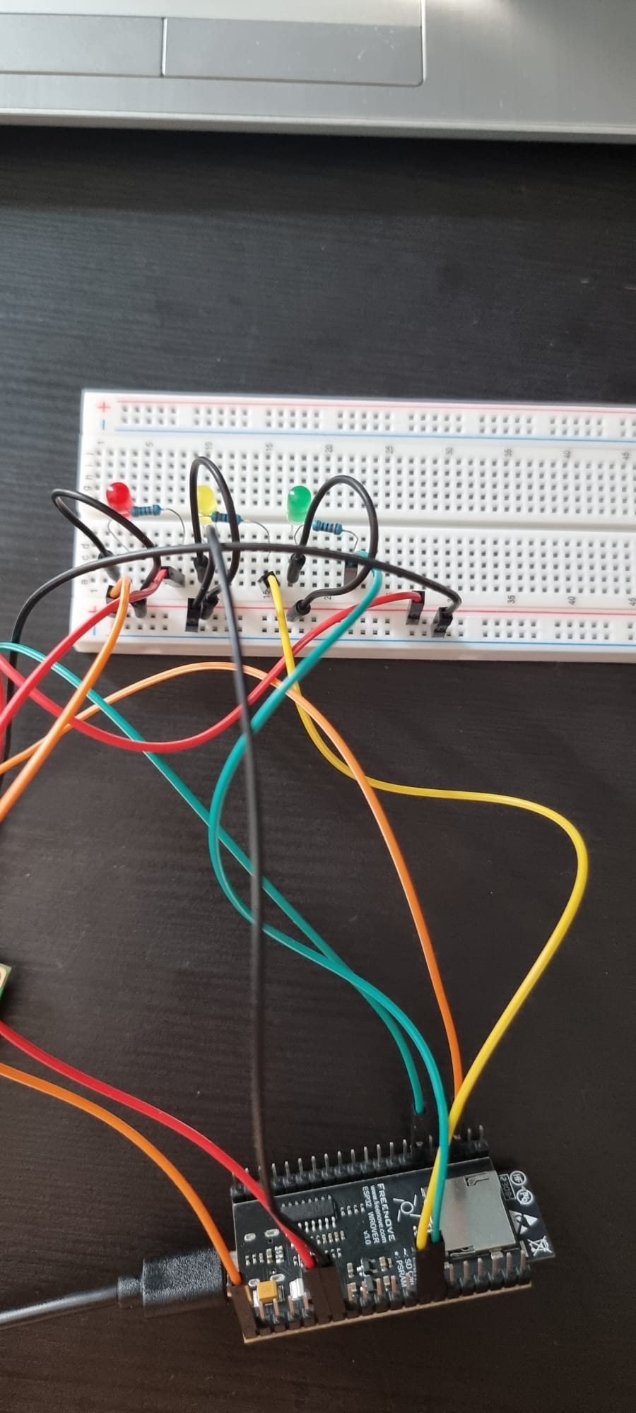
It is hard for me to follow your wires.
Make a drawing of your project. Draw an ESP32 (is that what you have?) with pin numbers and wires leading to resistors, label the LED anode (+) and cathode (-) and the power supply +/-... and post that drawing.
Wiring diagrams and schematics are a very important part of electronics. Use this as a way to convey your intentions of the project and the code you write.
Drawing your circuit also lets you "see" (your mind keeps track of many things without letting you know) if your wires are going to the right places.
If your circuit is not working, remove everything and start with just ONE resistor/LED and run your code... then when it works, add more.
Remember; ask any question.
this is NOT an arduino. U use NodeMCU V3 WIFI?
That Is not equivlant to arduino. Write the code in Lua and firstly learn lua
wrong wireing. Take off the ground and LCD.
Replace the VCC to red.
Gnd Is blue/black
also its entirely shorted
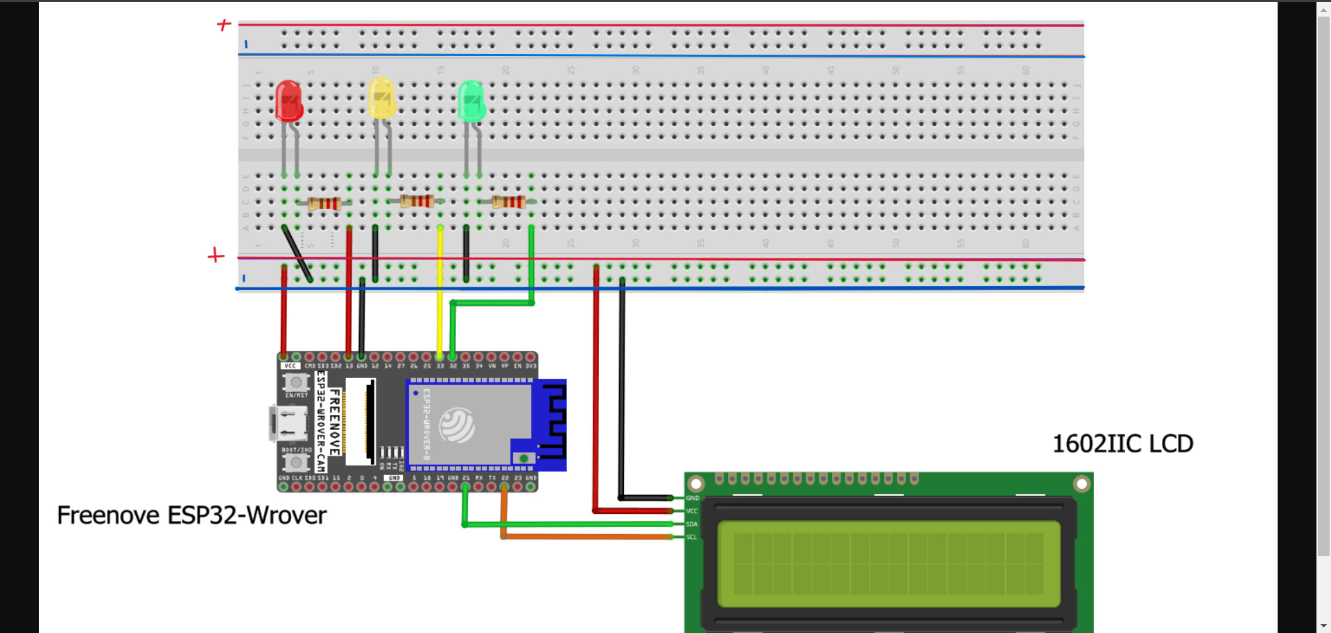
Include the power supply in your drawing.
the power suply is from the esp32 to Laptop! Its a cable!
Get in the habit of using a power supply, not the MCU. The MCU should be used for data, and maybe small (< 40mA) device power. Try this (drawing). Notice, the VCC from the ESP is removed. The ESP receives power from the PC/USB.

Doesn't the 'MCU', the dev_board, in this case, basically allow VUSB to pass through?
I do not assume VCC is passthrough.
The "tech ref" from the Wrover datasheet:
Page 18. wrong one.
https://www.espressif.com/sites/default/files/documentation/esp32-wroom-32_datasheet_en.pdf