I salvaged some NPN transistors from a circuit board I took out of an old washer. I recently moved and had to leave most of my electronics stuff behind (until I can get it shipped). Anywho, they're C547B (datasheet) transistors. Nothing fancy, but they're what I was looking for. I'm wanting to turn on and off lights and other AC devices in the shop, so I'm using the transistor to switch a relay, which I'll use to switch on the lights and fans, etc. The relay is being powered by an old computer power supply. After a lot of research, learning about the intricacies of transistors and calculating the resistor I need to switch the transistor with 5v from the arduino, I wired it all up. First I tested it would work by taking 5v from the power supply and sticking it into the base of the transistor (through the 15k resistor), and it all worked. Next, confident at least with my circuit, I stuck a jumper into the arduino's 5v pin and into the transistor and...nothing. Now, my momma didn't raise no dummy, so I assume that this is because the 5v going out of the arduino can't find its way back in. Before I try it, I want to make sure that I can share a common ground between the 12v from the power supply and the arduino. For now, I can just get a jumper wire and stick the pokey bit into the GND pin on the arduino, then into one of the GND pins of the power supply. I don't want to destroy my arduino though, so I want to make sure this is the normal convention.
Always connect the grounds.
Now, my momma didn't raise no dummy, so I assume that this is because the 5v going out of the arduino can't find its way back in. Before I try it, I want to make sure that I can share a common ground between the 12v from the power supply and the arduino. For now, I can just get a jumper wire and stick the pokey bit into the GND pin on the arduino, then into one of the GND pins of the power supply.
Yes, you need a "ground return" between the transistor and the Arduino so you need to connect the two grounds.
Without the ground there is no voltage across the base-emitter junction and no current flows into the base.
through the 15k resistor
If it works, fine... 15K "feels" a little high to me but I don't have the relay coil specs and I didn't look-up the transistor specs.
Read this :- Why you need to connect the grounds together
Thank you everyone! I was 99% sure that's what I needed to do. Like I said, I just didn't want to ruin my arduino.
DVDdoug:
If it works, fine... 15K "feels" a little high to me but I don't have the relay coil specs and I didn't look-up the transistor specs.
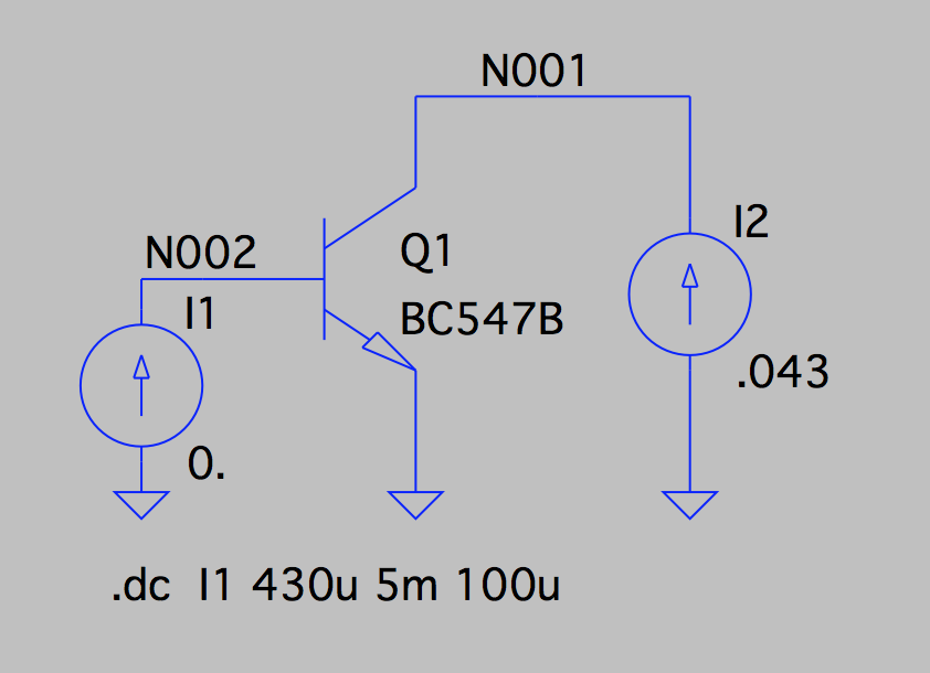
It's actually a 10k and a 4.7k in series. The relay uses 43mA at 12v, and the transistor has an hFE of around 200, so I did .043 / 200 and got .000215, rounded it to .25 mA to make sure I'm in saturation, then did (5 - .7) / .00025 and got 17200 for the resistor, so I just went nearest to what I had on hand, which was 14.7k. The transistor is getting around .3 mA at the base and about 60mA is flowing through the collector-emitter path.
Either 10K or 4K7 would have been fine, this sort of thing is not critical. Often you need more current to saturate a transistor than the gain would imply. This is because the exact gain is dependent on the collector current. In the data sheet for the transistor there will be a saturation voltage quoted. This will be at a certain current, it is that current you should use for your calculations.
Ib = Ic / 10 or Ib = Ic / 20 are common ratios to ensure that the C-E saturation voltage is nice and low.
The BC547 datasheet uses Ic / 20, so you want a base current of 43mA / 20 = 2.2mA.
Base-emitter saturation voltage will be about 800mV with a collector current of 43mA.
So with a 5V Arduino, the voltage across the resistor will be 4.2V.
4.2V / 2.2mA = 1909Ω. A 1.8KΩ or 2.2KΩ base resistor would be ideal. 15K is a bit large, as Doug said (and Mike implied).
The relay uses 43mA at 12v............about 60mA is flowing through the collector-emitter path
I don't get this. You only mentioned having the relay connected, and based your calculation on 43mA. Where does 60mA come from?
Grumpy_Mike:
Either 10K or 4K7 would have been fine, this sort of thing is not critical. Often you need more current to saturate a transistor than the gain would imply. This is because the exact gain is dependent on the collector current. In the data sheet for the transistor there will be a saturation voltage quoted. This will be at a certain current, it is that current you should use for your calculations.
Bad advice. The forced beta (hfe) used for the saturation measurement is totally arbitrary. In this particular spec it is 10 for fig. 4 and 20 for the "Electrical Characteristics" table. If you look at the graph of hfe vs collector current, the nominal hfe is 200 and flat out to around 100 mA. This is the graph you should be using. At your required current of 43 mA you have no beta rolloff so using the minimum spec hfe of 100 is fine. You do not need to go as low as 10. Also, the hfe rolloff curve is done at 5V. hfe actually slightly goes up at 12V collector voltage due to narrowing of the base at higher voltages.
At your required collector current of 43 mA and the minimum beta of 100 your transistor will saturate with .43 mA base current. This is guaranteed by the spec.
charliesixpack:
Bad advice. The forced beta (hfe) used for the saturation measurement is totally arbitrary. In this particular spec it is 10 for fig. 4 and 20 for the "Electrical Characteristics" table. If you look at the graph of hfe vs collector current, the nominal hfe is 200 and flat out to around 100 mA. This is the graph you should be using. At your required current of 43 mA you have no beta rolloff so using the minimum spec hfe of 100 is fine. You do not need to go as low as 10. Also, the hfe rolloff curve is done at 5V. hfe actually slightly goes up at 12V collector voltage due to narrowing of the base at higher voltages.At your required collector current of 43 mA and the minimum beta of 100 your transistor will saturate with .43 mA base current. This is guaranteed by the spec.
Not "bad advice" at all. It's quite normal to use a forced beta of 10 or 20 for switching. Using the quoted Hfe figure does ensure that the transistor is in saturation, as you rightly say, but only just.
At that point, though, Vce is not as low as it could possibly be, resulting in higher power dissipation in the transistor.
Forcing the beta to a lower value will decrease the Vce noticeably.
Not too important in this circuit, since dissipation is very low either way, but to say it's "bad advice" is wrong. It's a standard practice.
OldSteve:
At that point, though, Vce is not as low as it could possibly be, resulting in higher power dissipation in the transistor. Forcing the beta to a lower value will decrease the Vce noticeably.
This is not true. Look at fig. 1 of the transistor spec. When the transistor saturates all the base currents converge into a straight line on the characteristic curve. You can see on the graph that when Ic=20 mA then Vce is the same value for Ib=.15mA as for Ib=.4mA. In both cases Vce=.4V. The collector current dissipates 20mA*.4V=8mW in the transistor in both cases. But the base current dissipates .15mA*.8V=.06mW in the first case and .4mA*.8V=.32mW in the second case. Contrary to a noticeable decrease, the power dissipated in the transistor increases slightly as you increase base current.
There is no advantage to increasing base current in a saturated transistor.
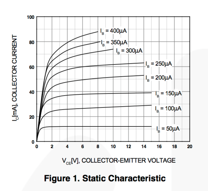
You're wrong, and just seeing what you want to see. With Ic =20mA, I see a slight difference between Vce at Ib = 150uA and Ib = 400uA
It's not a "straight line" at all. At 20mA, the line is much thicker than a 'single line'. (It's "noticeably" thicker, possibly 4-5 times as thick, but hard to see on this scale.)
You recommend about 430uA base current. I say 2mA to 4mA. If you were to draw a line on that graph for Ib = 2mA or Ib = 4mA, the Vce would be noticeably lower at Ic =43mA. It's true.
There is a very good reason that the datsheets quote Vce(sat) at a forced beta of 10 or 20.
I won't argue this further with you.
Real-world figures for a BC548B:-
Vcc = 12.7V
Vin = 5.0V
R(load) = 280 ohms (2 x 560 ohms in parallel)
With Rb = 10K:-
Vbe = 0.81V
Vce(sat) = 145mV
Ic = (12.7V - 0.145V) / 280 = 44.8mA
Ib = (5.0V - 0.81V) / 10K = 419uA
Hfe = 106.9
Pd(collector) = 145mV x 44.8mA = 6.5mW
Pd(base) = 419uA x 0.81V = 0.339mW
Pd (total) = 6.84mW
With Rb = 1.5K:-
Vbe = 0.85V
Vce(sat) = 97mV
Ic = (12.7V - 0.097V) / 280 = 45.0mA
Ib = (5.0V - 0.85V) / 1.5K = 2.77mA
Hfe = 16.2
Pd(collector) = 97mV x 45mA = 4.37mW
Pd(base) = 2.77mA x 0.85V = 2.35mW
Pd(total) = 6.72mW
So while in this case it wasn't much of a reduction, the power dissipation was reduced by increasing base current, not increased, and the voltage applied to the load was increased by almost 50mV. Vce(sat) was "noticeably" reduced. (By about 33%)
As I said earlier, in this case it makes very little difference, but when switching higher currents, and using some transistors, the benefit is considerably greater, and worth the effort.
OldSteve:
I won't argue this further with you.
Facts, no argument. I did a simulation for the exact device we are talking about under the exact conditions we are talking about.
horizontal axis = base current
vertical axis = power
total power = red
collector-emitter power = blue
base-emitter power = green

charliesixpack:
Facts, no argument. I did a simulation for the exact device we are talking about under the exact conditions we are talking about.
Yep. Note that at your recommended base current of 430uA, total dissipation is higher than at Ic/20, which is what I was saying all along, and my test showed the same. (According to the datasheet, although I used a BC548B for my test, the specs are identical.)
Looking at your graphed results, it's not until the base current reaches about 3.5mA with a forced beta of about 12 that total power dissipation gets back as high as it was with 430uA base current.
So the bottom line is that my recommended base resistor values of 1.8K to 2.2K from reply #6 would result in 1.9mA to 2.3mA base current, with a respective beta of 22 to 18.7 and total dissipation almost 1mW lower than with a base current of 430uA. Not quite ideal, (which I claimed), but pretty close.
OldSteve:
Yep. Note that at your recommended base current of 430uA, total dissipation is higher than at Ic/20, which is what I was saying all along
Well, no. Here is what you actually said...
OldSteve:
Forcing the beta to a lower value will decrease the Vce noticeably.
You have conveniently forgotten the forced beta of 10 that you mentioned was "standard practice". No matter. I think we have shown that you should never have brought up any power advantage in increasing base current. It is negligible even if you choose your base current to minimize it.
charliesixpack:
Well, no. Here is what you actually said...Forcing the beta to a lower value will decrease the Vce noticeably.
And that's perfectly true. There was a 33% reduction. You said there was no decrease in Vce as base current increases. That's not true.
You have conveniently forgotten the forced beta of 10 that you mentioned was "standard practice". No matter. I think we have shown that you should never have brought up any power advantage in increasing base current. It is negligible even if you choose your base current to minimize it.
I actually said 10 or 20, and in this case it's 20, as shown in the chart in the datsheet, and by my choice of a 1.8K or 2.2K resistor. From reply #8:-
It's quite normal to use a forced beta of 10 or 20 for switching. ........It's a standard practice.
The fact remains that it is a standard practice. And there is a power advantage, even if it is negligible in this case. Your own simulation graph shows that.
I don't come to this section of the forums as much any more, because everybody wants to argue, and today is no exception. Enough for me.
And it is important to realize that in saturation there is no transistor action at all by the normal mechanism,
the base-collector junction is forward biased, no charges are swept out to the collector due to the electric
field since the field is the wrong way.
The current gain in saturation is an entropy effect only due to the ratio of doping between emitter:base:collector
being about 10000:100:1 - its the diffusion of charge carriers that carry the current past the base into
the collector (overwhelming the normal forward-biased BC current).
For any high current application a saturation current gain of about 5 to 20 is common, though some newer
superbeta devices get to about 30 to 50. Remember this is when the base is more positive than the
collector, by perhaps 0.6V or more.
Often people wonder why an NPN device isn't symmetrical (emitter and collector are equivalent) - this is
the reason.
See, this is why I get confused. Y'all are throwing numbers around and I don't know where they came from. All I know is that in the datasheet, under "DC Current Gain" it had an hFE of 290 for 10mA @ 5V and 180 for 100mA @ 5V, so I picked something in between there since my desired current through the transistor was 43mA, and I came to 17.2k, I reduced it to 14.7k because that's what I had handy, and because I wanted to make sure the transistor was in saturation.
See, this is why I get confused.
Yes that is the problem when you mention a simple solution, all sorts of folks come up with things that might be strictly more precise but are unnecessarily complex. The problem is electronics is a bit like an onion. It has multi levels of complexity, but most of the time you only need one or two layers deep.
The problem is that the calculation you used is not strictly valid for the situation you used it in. The concept of a "forced gain" is that you assume some fictitious small value for the gain of the transistor in order to get it fully saturated. This is normally way smaller than the "small signal gain" figure which you thought was right to use. The result is that you underestimated the current needed. This is no great disaster it is just that collector / emitter voltage might not be as small as it could be.
The only effect of having too much base current is that it slightly slows down the speed the transistor turns off due to the miller effect. Again this is going down a few layers in the onion. I would be surprised however if this has any effect in what you want to achieve.
You can design the F*** out of a circuit and often it has no effect on the final project. But some times it does matter, and that is the secret of being good at electronics, knowing how deep to go. You will have noticed there are some people here who don't know where to stop and are critical of those who do.
HaLo2FrEeEk:
See, this is why I get confused. Y'all are throwing numbers around and I don't know where they came from. All I know is that in the datasheet, under "DC Current Gain" it had an hFE of 290 for 10mA @ 5V and 180 for 100mA @ 5V, so I picked something in between there since my desired current through the transistor was 43mA, and I came to 17.2k, I reduced it to 14.7k because that's what I had handy, and because I wanted to make sure the transistor was in saturation.
You did absolutely the right thing. You used a sensible approach. If you find that it does not work, you go back and find out where you went wrong. Don't let the forum noise confuse you.