This is still making my head hurt. This article agrees with what was told to me in this post, that hfe is irreverent when using the transistor as a switch. Then the author uses hfe to calculate the base resistor when using it as a switch?? Changing that number drastically changes the resistance in the calculation. If I am doing this correctly, I get the following using 100 for hfe.
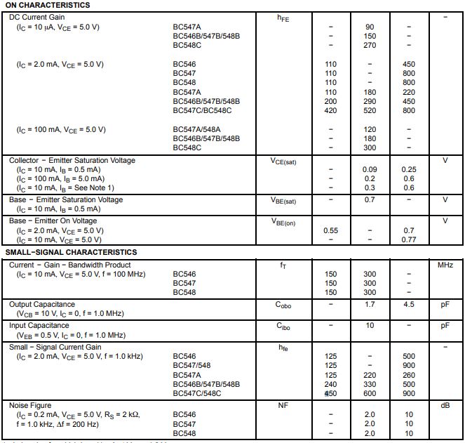
Attached is the actual data from the BC547B part I got from digikey. I actually have no idea which value I would use for minimum hfe in my scenario.
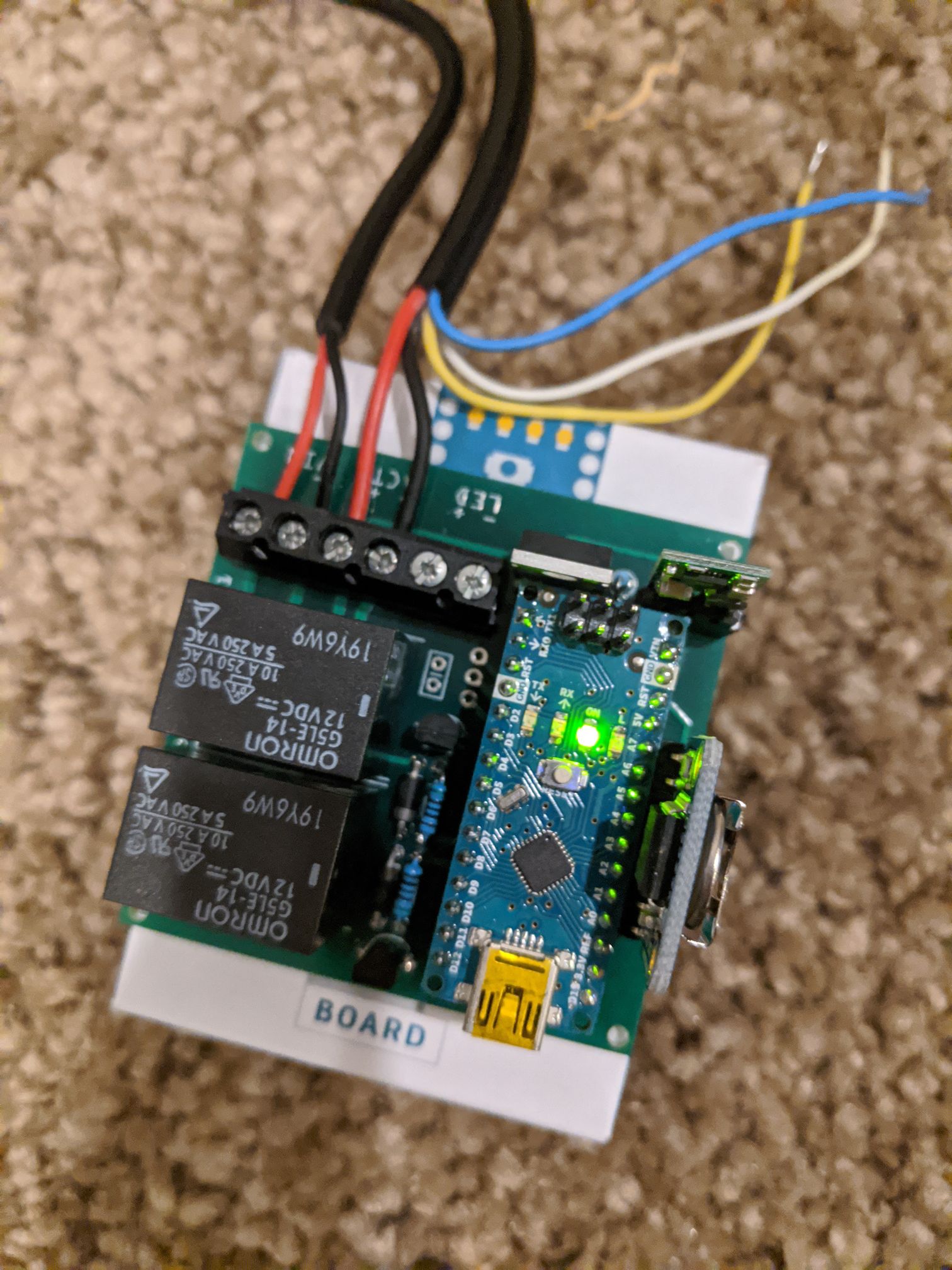
BASE TO CONTROL
The question now is how do you control the transistor so it turns on and off? Well, we have to do two things: 1. Find the correct transistor base current (IB) that will saturate the transistor. 2. Calculate the resistance value for the base resistor RB (see Figure 1). The formula for finding the base current is:
IB(EOS) = IC(MAX)
Beta (min)
Notice here, in order to find the base current (IB), we divide the maximum collector current (IC(MAX)) we want to go through the LED (15 mA) by the minimum Beta listed on the datasheet (hFE). What is Beta? Beta — also known as DC current gain — is a ratio relating to how much current gain you can expect through a transistor’s collector terminal given a certain amount of current going into the base terminal. In other words, the base current controls the collector current. It’s kind of like a small water valve controlling the flow of water running through a large pipe.
Having said all that — and this is very important — Beta (gain) is only used in amplifier design. When you’re using a transistor as a switch (digital mode), Beta has little effect or meaning because the transistor is not operating in the active region that amplifiers work in. Once a transistor switch is in saturation mode, there’s no collector current gain beyond saturation.
In other words, once a transistor switch reaches the saturation point, the gain formula IC = Beta x IB no longer applies because the voltage drop across the collector/emitter terminals (VCE(sat)) has reached its lowest saturation voltage of .1V. When VCE(sat) reaches this voltage level, the collector current can’t increase beyond this point — even if the base current continues to increase.
Remember, a transistor operating in digital mode (on/off) is either in saturation mode (fully switched on) or in cut-off mode (fully switched off). Therefore, any level of collector current (Ic) in between the two states of saturation and cut-off is not important to the functioning of a transistor switch — it’s only important to amplifier designers.
Okay, so what value do we use for Beta in the formula to find the base current (IB)? Well, the standard rule of thumb states that you should use the minimum Beta (hFE) listed on the datasheet. Unfortunately, the minimum Beta listed on the datasheet will only place the transistor at the Edge of Saturation (EOS). Since transistors are sensitive to temperature changes, a change in temperature could force the transistor to move from the EOS into the “active” area (amplifier region).
Therefore, in order to eliminate this possibility, we use what is known as an “Overdrive Factor” (ODF). This is an arbitrary number between 2 and 10 that is used to insure that the transistor is driven hard into saturation (fully turned on) — and where temperature changes fail to drop the transistor out of saturation. Therefore, IB equals:
IB = IB(EOS) x ODF
↓
IB = IC(MAX) x ODF
Beta (min)
IB = .015 x ODF
100
IB = .15 mA x 10
IB = 1.5 mA
Notice, in the formula above, by using an ODF of 10 we increase the base current from 150 µA to 1.5 mA, thereby assuring that the transistor is forced into deep saturation. For example, if a datasheet listed a Beta(min) of 75, and you needed a collector current (IC(MAX)) of 25 mA, IB would be .333 mA (.000333A). Unfortunately, 333 µA would only put the transistor at the EOS. By using an ODF of 10, we increase the base current (IB) to 3.3 mA — well beyond the EOS and into deep saturation.
Now that we have established a base current (IB) of 1.5 mA is required to saturate our transistor, let’s calculate the resistance value needed for the base resistor RB. Once again, we use Ohm’s Law to calculate for RB:
RB = VIN - VBE(sat)
IB
RB = 5 - .6
.0015
RB = 2933.33 ohms