I would like to share with you my last project, a transistor curve tracer using Arduino.
The idea is simple, i. e., to obtain the output I-V curves of a BJT by reading the voltage drops at the transistor when separate voltage sweeps at base and collector are applied (using a couple of DAC converters).
The project is conceived for educational purposes, so I do not expect to get very accurate curves as those provided by professional (and expensive) characterization systems. I intend just to be able to show to the students reasonable and realistic I-V curves corresponding to the discrete transistors they are using in lab work, getting those curves in the same lab for each specific transistor.
Up to now I've developed the Arduino sketch, that you may find below. The results are printed to the serial output, so you just need to copy&paste them to your favourite plotting software (Excel, SigmaPlot, etc.) to get the curves (just take into account that the data are repeated each time the main loop is run). The next step is to develop some Processing code to plot the results directly, getting the average values for several runs. In any case, all ideas about how to improve the project are welcome!
Here's the circuit (all connections are explained at the sketch)
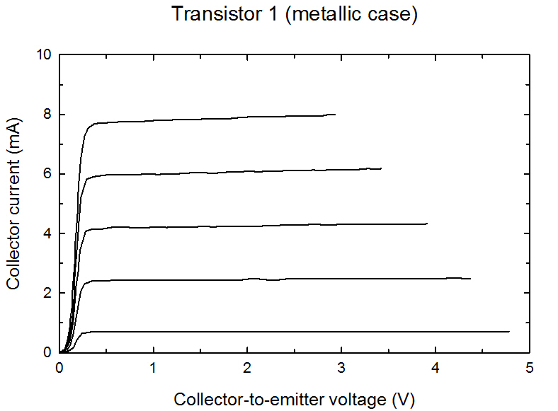
And a couple of measuments I did with two different npn transistors
And finally, the Arduino sketch
/*
Transistor curve tracer

This is the Arduino sketch for a transistor curve tracer.
Two 12-bit MCP4921 Digital-to-Analog (DAC) converters are used
to sweep the base and collector voltages and provide the output
characteristics. A 16-bit word needs to be written to the DAC
to set the analog voltage.

The circuit:

* Arduino pin 11 (MOSI) to pin 4 of both DACs
* Arduino pin 13 (CLK) to pin 3 of both DACs
* Arduino pin 10 to DAC1 pin 2
* Arduino pin 9 to DAC2 pin 2
* DACs pins 1 and 6 to 5V
* DACs pin 7 to GND
* DAC1 pin 8 (analog output) to base resistance RB
* DAC2 pin 8 (analog output) to collector resistance RC
* Transistor emitter to GND
* Transistor base to RB
* Transistor collector to RC

created 20 Aug 2011

by Raul Rengel
*/

//Including the SPI library
#include <SPI.h>

//Slave Select (SS) pins for the base (10) and the collector (9)
// SSbase corresponds to DAC1, and SScollector to DAC2
const int SSBase = 10;
const int SSCollector = 9;

//Number of different values to be considered for base
//and collector voltages
const int sweepbase = 5;
const int sweepcollector = 50;

//Voltages to be measured (analog inputs)
// VCE - Collector-to-Emitter
const int VCE_Pin = 0;
// VCC - To output of DAC1 (pin 8)
const int VCC_Pin = 1;
// VBE - Base-to-Emitter
const int VBE_Pin = 2;
// VBB - To output of DAC2 (pin 8)
const int VBB_Pin = 3;

// Values read at the analog inputs of Arduino
int vceValue = 0;
int vccValue = 0;
int vbeValue = 0;
int vbbValue = 0;

//Step for the base and collector voltages;
int vstepbase = 4095/sweepbase;
int vstepcollector = 4095/sweepcollector;

//Values in volts
float vce = 0;
float vbb = 0;
float vcc = 0;
float vbe = 0;

//For the RC and RB values, change the values to your own
float Rcollector = 220.0; //Collector resistance (ohm)
float Rbase = 99900.0; //Base resistance (ohm)
float Icollector = 0; //Collector current
float Ibase = 0; // Collector base

void setup() {
  //Set SS pins as outputs
  pinMode(SSBase,OUTPUT);
  pinMode(SSCollector,OUTPUT);

  //Initialize the SPI Bus
  SPI.begin();

  //Transfer MSB first according to the MP4921 datasheet
  SPI.setBitOrder(MSBFIRST);

  //Set initial values for VBB and VCC (avoids some problems
  // with the first values to be read)
  dacTransfer(SSBase, 1);
  dacTransfer(SSCollector, 1);

  //Initialize serial
  Serial.begin(9600);
}

void loop() {
     for (int i=vstepbase; i <= 4095; i=i+vstepbase){
       for (int j=vstepcollector; j <= 4095; j=j+vstepcollector){
         dacTransfer(SSBase, i);
         dacTransfer(SSCollector, j);
         delay(100);
         readValues();
       }
     }
}

void dacTransfer(int slaveNumber, int value){
// 16-bit value is splitted into two bytes
// 4 most significant bits correspond to configuration of the DAC
// 12 least significant bits correspond to 12-bit data

  byte upperData = 0x30;  // Set the 4 configuration bits
  byte lowerData = 0x00;
  word dataWord; // The 16-bit word to be written

  dataWord = value;
  lowerData = lowByte(dataWord);

//transfer the 4 most significant bits of data to the upper byte
  upperData |= highByte(dataWord);

//Select the DAC
  digitalWrite(slaveNumber,LOW);

//Transfer the data
  SPI.transfer(upperData);
  SPI.transfer(lowerData);

//DAC is unselected
  digitalWrite(slaveNumber,HIGH);
}

void readValues() {

//Read the values at the analog inputs
  vbbValue = analogRead(VBB_Pin);
  vbeValue = analogRead(VBE_Pin);
  vccValue = analogRead(VCC_Pin);
  vceValue = analogRead(VCE_Pin);

//Convert to volts
  vce=(float)vceValue*5./1023.;
  vcc=(float)vccValue*5./1023.;
  vbb=(float)vbbValue*5./1023.;
  vbe=(float)vbeValue*5./1023.;

//Calculate collector and base currents
  Icollector=(vcc-vce)/Rcollector*1000.;
  Ibase=(vbb-vbe)/Rbase*1000000.;

//Print to serial output
// VCC, VBB, VBE, IC (mA), IB (uA)
  Serial.print(vcc);
  Serial.print("\t");
  Serial.print(vbb);
  Serial.print("\t");
  Serial.print(vbe);
  Serial.print("\t");
  Serial.print(vce);
  Serial.print("\t");
  Serial.print(Icollector);
  Serial.print("\t");
  Serial.print(Ibase);

  Serial.println();

  delay(10);
}