I'm attempting to test a 2N3904 Transistor with an Arduino UNO R3, for starters I believe I haven't coded the program correctly. Secondly I'm not sure if I understand the Transistor correctly either.
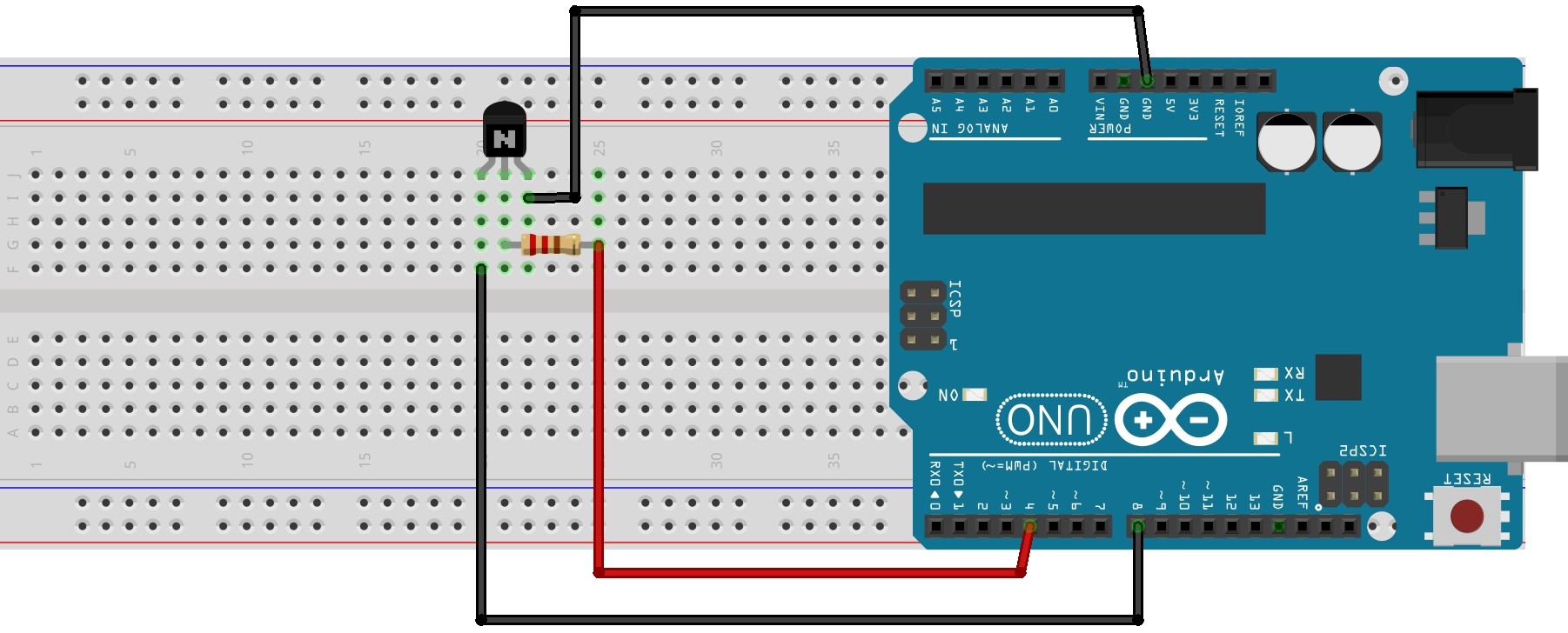
I have the 2N3904 Transistor on a breadboard, I have a connection going from Pin 4 of the Arduino to one end of a 10K resistor, the other end of the resistor going to the Base Pin of the 2N3904.
The Collector Pin is connected to Ground of the Arduino, the Emitter Pin to Pin 8 on the Arduino.
The Code:
/*
* Components: Breadboard; Arduino UNO R3; 2N3904 Transistor; 10K Resistor; Jump wires.
*
* Digital Pin 4 from Arduino connected to 10K Resistor
* 10K resistor connected to Base Pin of 2N3904 Transistor
* Collector Pin of 2N3904 Transistor connected to Arduino Ground Pin
* Emitter Pin of 2N3904 Transistor connected to Pin 8 of Arduino
*/


byte BasePin = 4;                       //Base Pin of 2N3904 Transistor to Pin 4 of Arduino UNO R3
byte EmitterPin  = 8;                   //Emitter Pin of 2N3904 Transistor to Pin 8 of Arduino UNO R3

long BAUD = 115200;                     //BAUD rate for Serial Monitior

unsigned long currentMillis;            //For saving current time
unsigned long previousMillis1 = 0;      //For storing Previous time
unsigned long previousMillis2 = 0;      //For storing Previous time
unsigned long TransistorOnTime = 4000;  //Turn transistor on for 4000ms
unsigned long TransistorOffTime = 2000; //Turn transistor off for 2000ms
unsigned long Read_Emitter = 1000;      //Read state of Emitter pin every 1000ms

void setup()
{
  Serial.begin(BAUD);                 //Start Serial for troubleshooting

  pinMode(BasePin, OUTPUT);           //Pin 4 set as OUTPUT
  digitalWrite(BasePin, LOW);         //Set Pin 4 LOW

  pinMode(EmitterPin, INPUT_PULLUP);  //Set pin 8 as INPUT_PULLUP

  Serial.println("Program Begin..."); //Print something on the Serial Monitor so I know program has started
  Serial.println();                   //Print a blank line to the Serial Monitor
}

void loop()
{
  currentMillis = millis();       //Track time through each loop
  Pulse_Send();                   //Sub Routine for sending pulses to the 2N3904 Transistor Base Pin
  Pulse_Read();                   //Sub Routine for receiving pulses from the 2N3904 Transistor Emitter Pin
}


void Pulse_Send()
{
  if (currentMillis - previousMillis1 >= TransistorOnTime)        //IF Current time - Previous time is greater than 4000ms
  {
    digitalWrite(BasePin, HIGH);                                  //Set digital Pin 4 HIGH
    Serial.println("BasePin High");                               //Display on Serial monitior so I can see it did it
    previousMillis1 = currentMillis;                              //Update perviousMillis1 to current time
  }
  else if (currentMillis - previousMillis1 >= TransistorOffTime)  //IF Current time - Previous time is greater than 2000ms
  {
    digitalWrite(BasePin, LOW);                                   //Set digital Pin 4 LOW
    Serial.println("BasePin Low");                                //Display on Serial monitior so I can see it did it
    previousMillis1 = currentMillis;                              //Update perviousMillis1 to current time
  }
}


void Pulse_Read()
{
  if (currentMillis - previousMillis2 >= Read_Emitter)            //IF Current time - Previous time is greater than 1000ms
  {
    if (EmitterPin == LOW)                                        //IF Digital Pin 8 == LOW
    {
      Serial.println("Signal Received (low)");                    //Display on Serial monitior so I can see it did it
      Serial.println();                                           //Print a blank line to Serial Monitor
      previousMillis2 = currentMillis;                            //Update perviousMillis2 to current time
    }
    else if (EmitterPin == HIGH)                                  //IF Digital Pin 8 == HIGH
    {
      Serial.println("No Signal Received (Input Pullup holding Pin High)"); //Display on Serial monitior so I can see it did it
      Serial.println();                                                     //Print a blank line to Serial Monitor
      previousMillis2 = currentMillis;                                      //Update perviousMillis2 to current time
    }
  }
}
When I run the program & view the Serial Monitor, I only see "BasePin LOW" it doesn't go HIGH but if change unsigned long TransistorOnTime = 4000; to unsigned long TransistorOnTime = 2000; and then do the same for the off time From: unsigned long TransistorOffTime = 2000; To: unsigned long TransistorOffTime = 4000; The result from the Serial Monitor is always "BasePin HIGH". My Subroutine "void Pulse_Read()" is not returning any results on the Serial Monitor in either case.
Have I tried to base the coding off of the Blink Without Delay / Flash Without Delay examples.
I have tried to draw up the hardware in Fritzing except I couldn't make the resistor a 10K.
Which means the colector is typically connected to Vcc and the Emitter to Ground.
COnnecting Collector-Emitter to two Arduino-IO-pins means if you configure the two IO-pins wrong you create a shortcut between the two IO-pins that will destroy the microcontroller.
As you seem to have no knowledge about electronics I recommend that you follow
very well explained tutorial or to use additional current-limiting resistors of 1 kilo-ohm everyhwere
In some cases the current-limiting resistor will have a "bad" influence on the behaviour of the electronics but this is rather seldom. But in most cases it will do what the name says: limiting the current that makes your microcontroller survive in case of wrong connections.
Thanks for the reply Stefan, my poor Arduino UNO has been through many short circuits I believe LOL I have very limited circuit knowledge but its so fascinating to learn about! Unfortunately I have read the data sheet for this transistor many times but it just seems to confuse me more & more each time I read it. I think I better find some 1K resistors to give my Arduino a well deserved break from my abuse.
Thanks again for the hardware tips, just need someone to take a peak at my poor coding now.
Hi, I'm using a numbered list, so you can refer to that number.
The emitter should be connected to GND and the collector to pin 8. A resistor of 220 Ω will work, but you better use 1k or 10k. Please show us a photo of the transistor and the wiring after fixing it.
Change "EmitterPin" to "CollectorPin" in the sketch.
A millis-timer with different on and off times should have just one previousMillis = currentMillis. I prefer to solve the different times inside the millis-timer. An example is my millis_different_on_and_off_times.ino. Can you fix that in Pulse_Send() ? I suggest you make a small test-sketch and test it with a led.
The EmitterPin variable is the number 8. It is never HIGH or LOW. Have another look at the Blink Without Delay example. Fix your Pulse_Read() to do something every second and use digitalRead() to read the input pin.
Show us the new sketch.
If you want to try my examples with a few clicks, then you can try the Wokwi simulations on my Fun With Millis page.
I do have a couple of multimeters (cheap one & good one), I even recently purchased an Oscilloscope (DSO 112A). Tutorial 2 on the link you posted looks good for me to try.
/*
* Components: Breadboard; Arduino UNO R3; 2N3904 Transistor; 10K Resistor; Jump wires.
*
* Digital Pin 4 from Arduino connected to 10K Resistor
* 10K resistor connected to Base Pin of 2N3904 Transistor
* Emitter Pin of 2N3904 Transistor connected to Arduino Ground Pin
* Collector Pin of 2N3904 Transistor connected to Pin 8 of Arduino
*/


byte BasePin = 4;                       //Base Pin of 2N3904 Transistor to Pin 4 of Arduino UNO R3
byte CollectorPin  = 8;                 //Collector Pin of 2N3904 Transistor to Pin 8 of Arduino UNO R3

long BAUD = 115200;                     //BAUD rate for Serial Monitior

unsigned long currentMillis;            //For saving current time
unsigned long previousMillis1 = 0;      //For storing Previous time
unsigned long previousMillis2 = 0;      //For storing Previous time
unsigned long TransistorOnTime = 4000;  //Turn transistor on for 4000ms
unsigned long TransistorOffTime = 2000; //Turn transistor off for 2000ms
unsigned long Read_Collector = 1000;    //Read state of Collector pin every 1000ms

void setup()
{
  Serial.begin(BAUD);                 //Start Serial for troubleshooting

  pinMode(BasePin, OUTPUT);           //Pin 4 set as OUTPUT
  digitalWrite(BasePin, LOW);         //Set Pin 4 LOW

  pinMode(CollectorPin, INPUT);       //Set pin 8 as INPUT

  Serial.println("Program Begin..."); //Print something on the Serial Monitor so I know program has started
  Serial.println();                   //Print a blank line to the Serial Monitor
}

void loop()
{
  currentMillis = millis();       //Track time through each loop
  Pulse_Send();                   //Sub Routine for sending pulses to the 2N3904 Transistor Base Pin
  Pulse_Read();                   //Sub Routine for receiving pulses from the 2N3904 Transistor Collector Pin
}


void Pulse_Send()
{
  if (currentMillis - previousMillis1 >= TransistorOnTime)        //IF Current time - Previous time is greater than 4000ms
  {
    digitalWrite(BasePin, HIGH);                                  //Set digital Pin 4 HIGH
    Serial.println("BasePin High");                               //Display on Serial monitior so I can see it did it
    previousMillis1 = currentMillis;                              //Update perviousMillis1 to current time
  }
  else if (currentMillis - previousMillis1 >= TransistorOffTime)  //IF Current time - Previous time is greater than 2000ms
  {
    digitalWrite(BasePin, LOW);                                   //Set digital Pin 4 LOW
    Serial.println("BasePin Low");                                //Display on Serial monitior so I can see it did it
    previousMillis1 = currentMillis;                              //Update perviousMillis1 to current time
  }
}


void Pulse_Read()
{
  if (currentMillis - previousMillis2 >= Read_Collector)            //IF Current time - Previous time is greater than 1000ms
  {
    if (digitalRead(CollectorPin) == LOW)                           //IF Digital Pin 8 == LOW
    {
      Serial.println("Signal Received (low)");                      //Display on Serial monitior so I can see it did it
      Serial.println();                                             //Print a blank line to Serial Monitor
    }
    else if (digitalRead(CollectorPin) == HIGH)                     //IF Digital Pin 8 == HIGH
    {
      Serial.println("No Signal Received (Input Pullup holding Pin High)"); //Display on Serial monitior so I can see it did it
      Serial.println();                                             //Print a blank line to Serial Monitor
    }
    previousMillis2 = currentMillis;                                //Update perviousMillis2 to current time
  }
}
Where is your pullup resistor? A transistor can not work without collector resistor. You should use either external resistor from collector to 5V or internal input pullup resistor by pinMode(CollectorPin, INPUT_PULLUP);
When there is base current that connection of a transistor can cause a very high current through the transistor, blowing it up and possibly damaging the power supply.
YES you are right!. If the collector is directly connected to Vcc without any current-limiting "thing" LED, resistor, relay-coil or whatever this is a shortcut.
It has to be connected like that
for NPN-transistors
Emitter to GND collector to a resistor (or any other load)
My description was too short I wanted to say it is very unusal to connect
emitter and collector to IO-pins.
Your PulseSend() is not okay. The combination of millis() with "if .. else if ..." does not work. Have you tested my example in the Wokwi simulation ? Have you made a small test-sketch to blink a led with different on and off times ?
Hi ya Boffin, I was using INPUT_PULLUP originally but it didn't appear to work like that,,, changing it to just INPUT & now it seems to be able to read high and low.
Using what circuit? There have been a lot of suggestions, and no word from you about what if any changes you've made to it. If it's the Fritzing in reply #8, and the above statement is true, then you have a wiring or transistor fault.
Hi Koepel, being able to see a simulation is nifty. I have done the Blink without delay and the flash without delay earlier on, with this current sketch I'm not checking the state of an LED, I just want it to do an instruction at the given time. Do I need to have it check for a state? I could setup a bool & have it update.
The correct sequence for testing is to set the conditions and then sample, i.e.
Apply test voltage to the base resistor
measure the collector voltage
apply zero volts to the base resistor
measure the collector voltage
compare the results of #2 and #4
Transistors operate in the microsecond time scale. You don't need millis() to sequence this. Only a few microsecond delays. In fact, if you follow a sequence carefully, no explicit (coded) delays are necessary at all.
For this to work, it goes without saying, your circuit has to be correct, the transistor must have the correct bias conditions.
Please post an image of your actual hardware. Frequently on this forum, we see a difference between a plan and an execution.
/*
* Components: Breadboard; Arduino UNO R3; 2N3904 Transistor; 10K Resistor; Jump wires.
*
* Digital Pin 4 from Arduino connected to 10K Resistor
* 10K resistor connected to Base Pin of 2N3904 Transistor
* Emitter Pin of 2N3904 Transistor connected to Arduino Ground Pin
* Collector Pin of 2N3904 Transistor connected to Pin 8 of Arduino
*/


byte BasePin = 4;                       //Base Pin of 2N3904 Transistor to Pin 4 of Arduino UNO R3
byte CollectorPin  = 8;                 //Collector Pin of 2N3904 Transistor to Pin 8 of Arduino UNO R3

long BAUD = 115200;                     //BAUD rate for Serial Monitior

unsigned long currentMillis;            //For saving current time
unsigned long previousMillis1 = 0;      //For storing Previous time
unsigned long previousMillis2 = 0;      //For storing Previous time
unsigned long TransistorOnTime = 4000;  //Turn transistor on for 4000ms
unsigned long TransistorOffTime = 2000; //Turn transistor off for 2000ms
unsigned long Read_Collector = 1000;    //Read state of Collector pin every 1000ms

void setup()
{
  Serial.begin(BAUD);                 //Start Serial for troubleshooting

  pinMode(BasePin, OUTPUT);           //Pin 4 set as OUTPUT
  digitalWrite(BasePin, LOW);         //Set Pin 4 LOW

  pinMode(CollectorPin, INPUT);       //Set pin 8 as INPUT

  Serial.println("Program Begin..."); //Print something on the Serial Monitor so I know program has started
  Serial.println();                   //Print a blank line to the Serial Monitor
}

void loop()
{
  currentMillis = millis();       //Track time through each loop
  Pulse_Send();                   //Sub Routine for sending pulses to the 2N3904 Transistor Base Pin
  Pulse_Read();                   //Sub Routine for receiving pulses from the 2N3904 Transistor Collector Pin
}


void Pulse_Send()
{
  if (currentMillis - previousMillis1 >= TransistorOnTime)        //IF Current time - Previous time is greater than 4000ms
  {
    digitalWrite(BasePin, HIGH);                                  //Set digital Pin 4 HIGH
    Serial.println("BasePin High");                               //Display on Serial monitior so I can see it did it
    previousMillis1 = currentMillis;                              //Update perviousMillis1 to current time
  }
  else if (currentMillis - previousMillis1 >= TransistorOffTime)  //IF Current time - Previous time is greater than 2000ms
  {
    digitalWrite(BasePin, LOW);                                   //Set digital Pin 4 LOW
    Serial.println("BasePin Low");                                //Display on Serial monitior so I can see it did it
    previousMillis1 = currentMillis;                              //Update perviousMillis1 to current time
  }
}


void Pulse_Read()
{
  if (currentMillis - previousMillis2 >= Read_Collector)            //IF Current time - Previous time is greater than 1000ms
  {
    if (digitalRead(CollectorPin) == LOW)                           //IF Digital Pin 8 == LOW
    {
      Serial.println("Signal Received (low)");                      //Display on Serial monitior so I can see it did it
      Serial.println();                                             //Print a blank line to Serial Monitor
    }
    else if (digitalRead(CollectorPin) == HIGH)                     //IF Digital Pin 8 == HIGH
    {
      Serial.println("No Signal Received (Input Pullup holding Pin High)"); //Display on Serial monitior so I can see it did it
      Serial.println();                                             //Print a blank line to Serial Monitor
    }
    previousMillis2 = currentMillis;                                //Update perviousMillis2 to current time
  }
}
I changed line 30 From: pinMode(CollectorPin, INPUT_PULLUP); //Set pin 8 as INPUT
To: pinMode(CollectorPin, INPUT); //Set pin 8 as INPUT
and then placed my jump wire going to Pin 8 on the Arduino onto the 5V rail,,, then the Ground Rail. It reflected correctly on the Serial Monitor,,,, when it was set as INPUT_PULLUP it was always stay HIGH even if I grounded it,,, no idea why.
You are saying that you connected an I/O pin directly to 5V or ground... that can destroy the pin.
I don't have a pinout for your transistor (a major problem already with your Fritzing, it's unlabeled), but assuming it goes ECB from left to right, you are driving the base directly from an I/O pin (a big no-no) and your collector is not connected to anything except an I/O pin. I don't see how it would be possible to test a transistor at all this way. There is no signal feed back to the Arduino because although you can bias the collector using the I/O pin, you can't simultaneously measure the current there.
Pay special attention to reply #13.
Have you tried Googling, "Arduino transistor tester"?