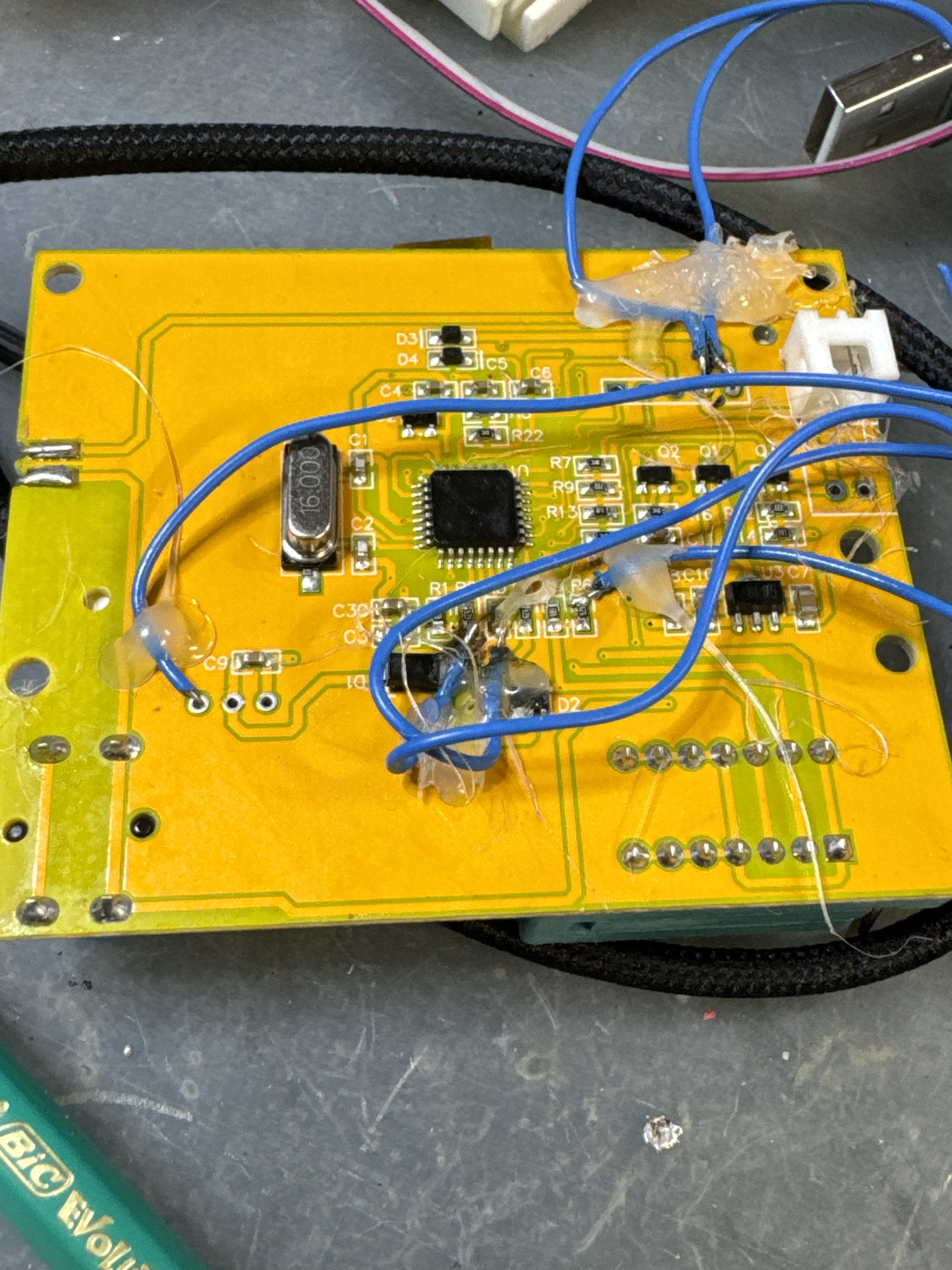
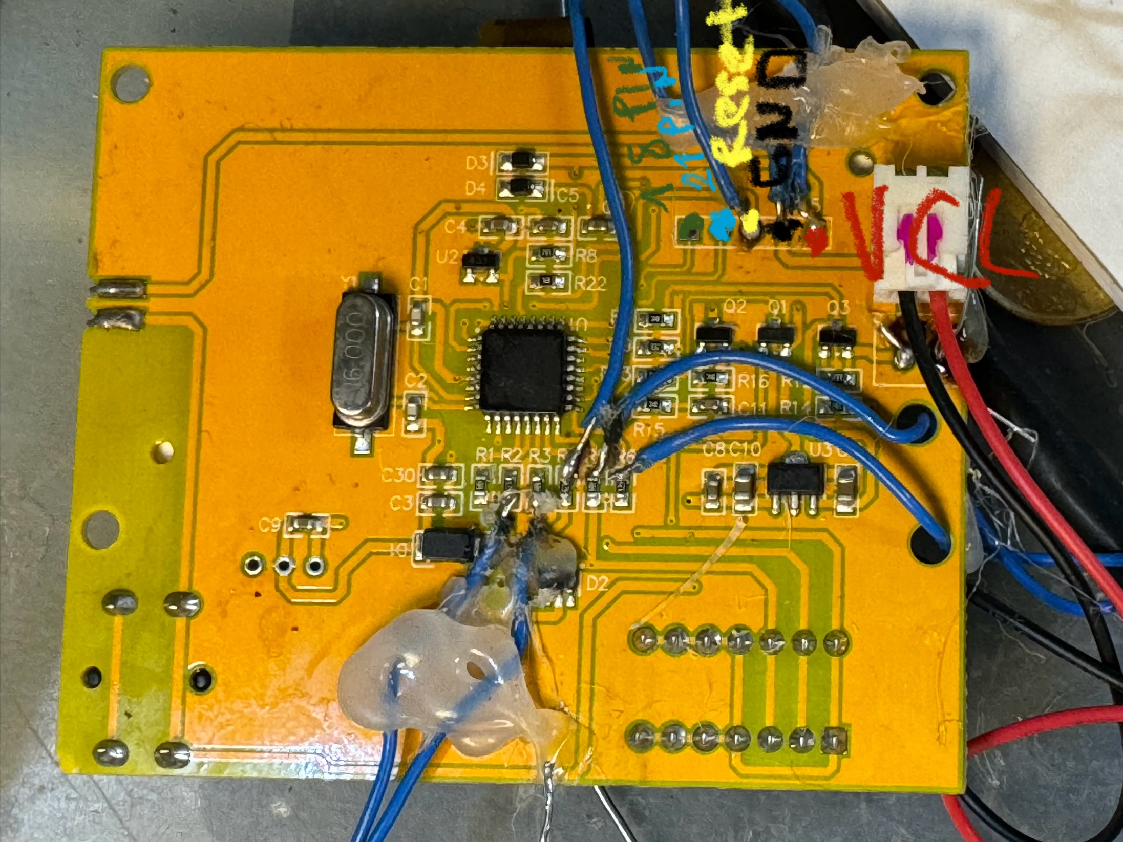
I bought a transistor tester (LCR-T4 clone) from China about 3 or 4 years ago. It has Chinese firmware, and now I’d like to update and flash new firmware. However, the board doesn’t have any ISP header or programming pins, and I can’t read the chip marking either — it seems to be blank or covered.
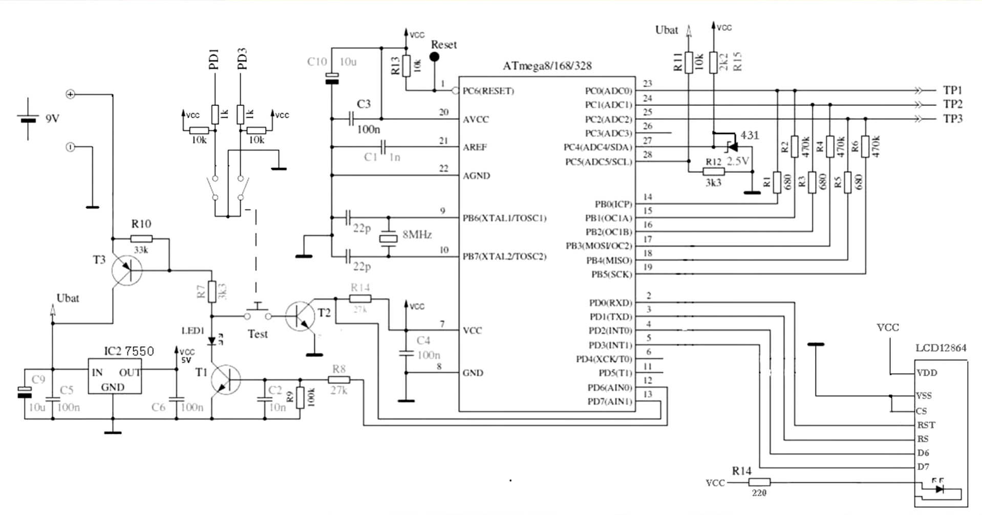
Based on the PCB traces, I believe the microcontroller is probably an ATmega328P (TQFP-32 package). For reference, pin 1 is likely RESET, pin 4 is VCC, and GND is connected to both pin 5 and pin 25.
Can anyone help confirm if this chip is indeed an ATmega328P, or provide tips for flashing it?
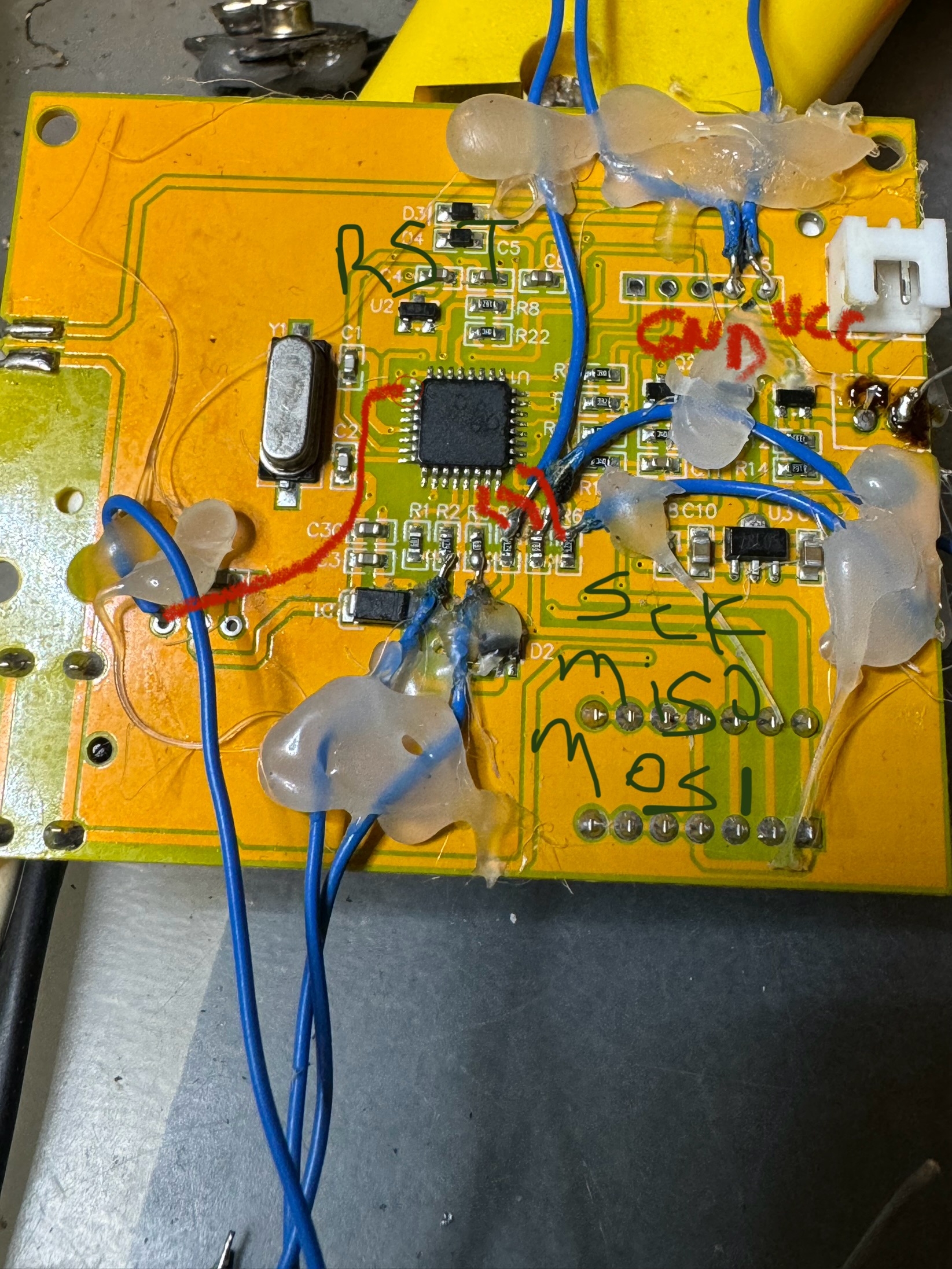
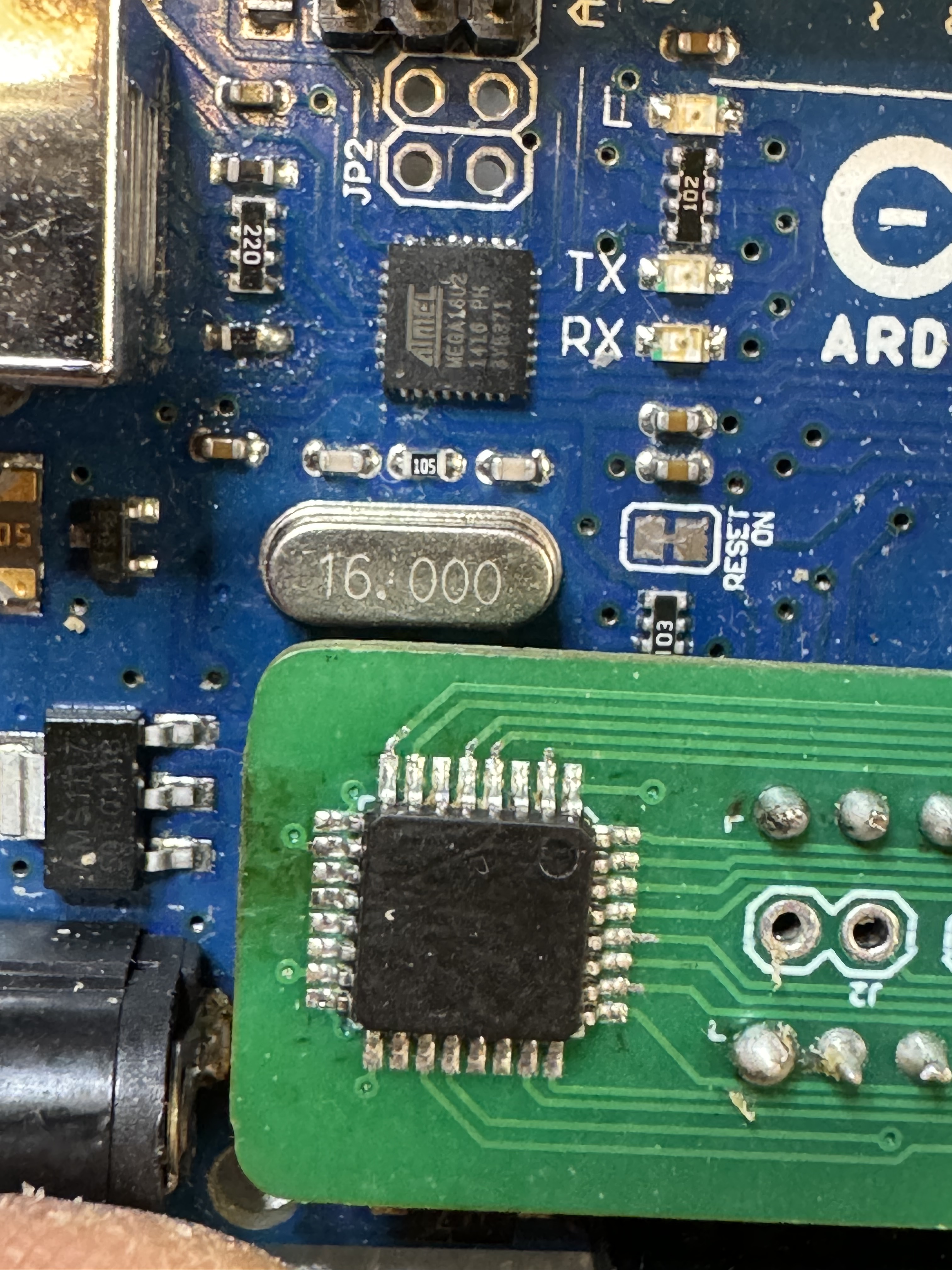
I think this one is different. It has a 16 MHz crystal, and it looks like pin 1 is RESET, pin 17 is SCK, pin 16 is MISO, and pin 15 is MOSI. These pin assignments are different from the typical schematics I’ve seen.
However, even with my wiring setup, avrdude doesn’t get any response from the chip.
Thank you for the support so far. Unfortunately, I still haven’t been able to get a response from the microcontroller.
Here’s what I’ve done:
• I confirmed that pin 5 is GND, and pin 4 is VCC — which matches the standard ATmega328P TQFP32 layout.
• Interestingly, pin 25 also seems to be connected to GND on my tester board, whereas on a typical ATmega328P, pin 25 is ADC2 (PC2). This is unusual and might be a clue.
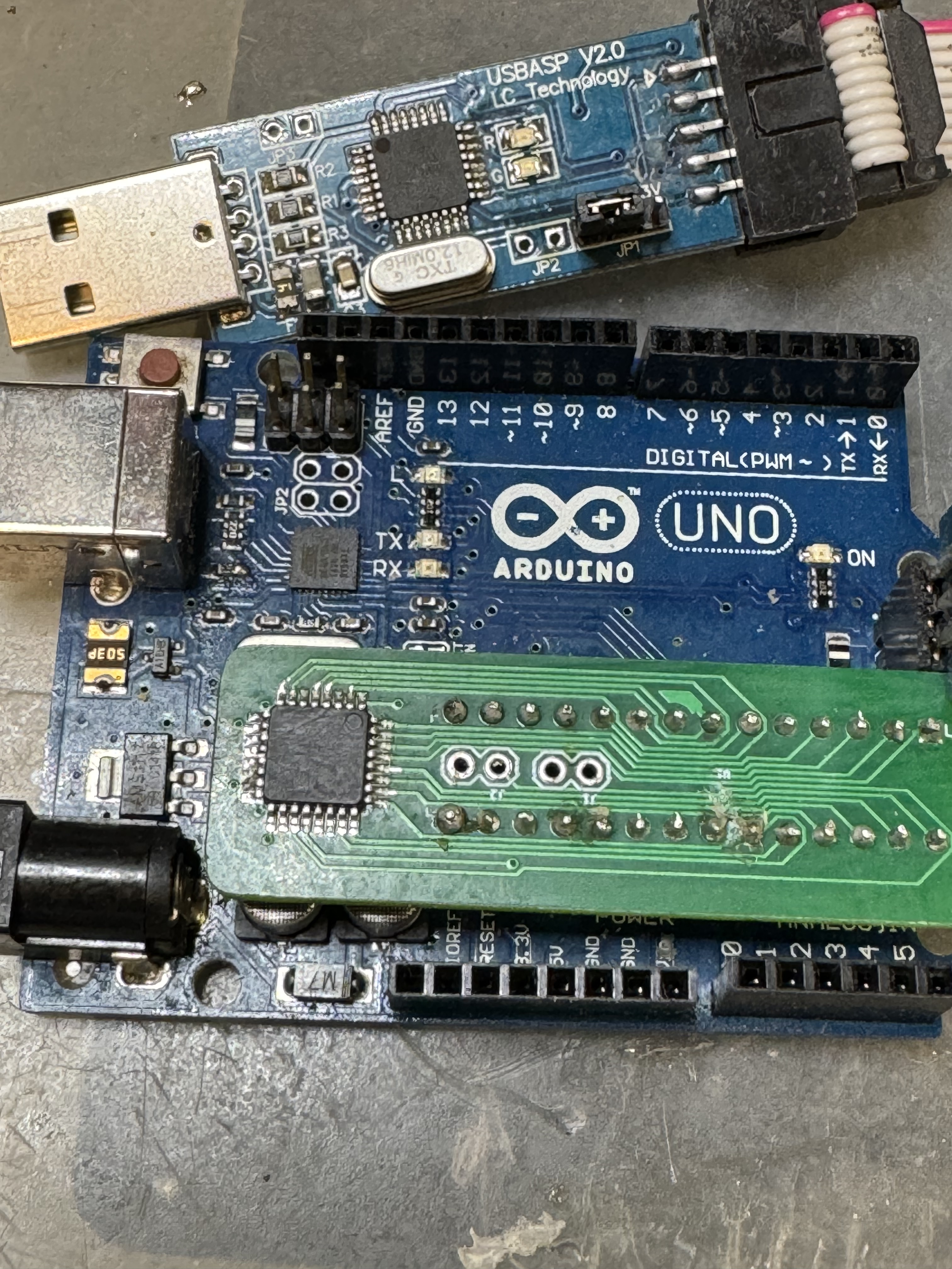
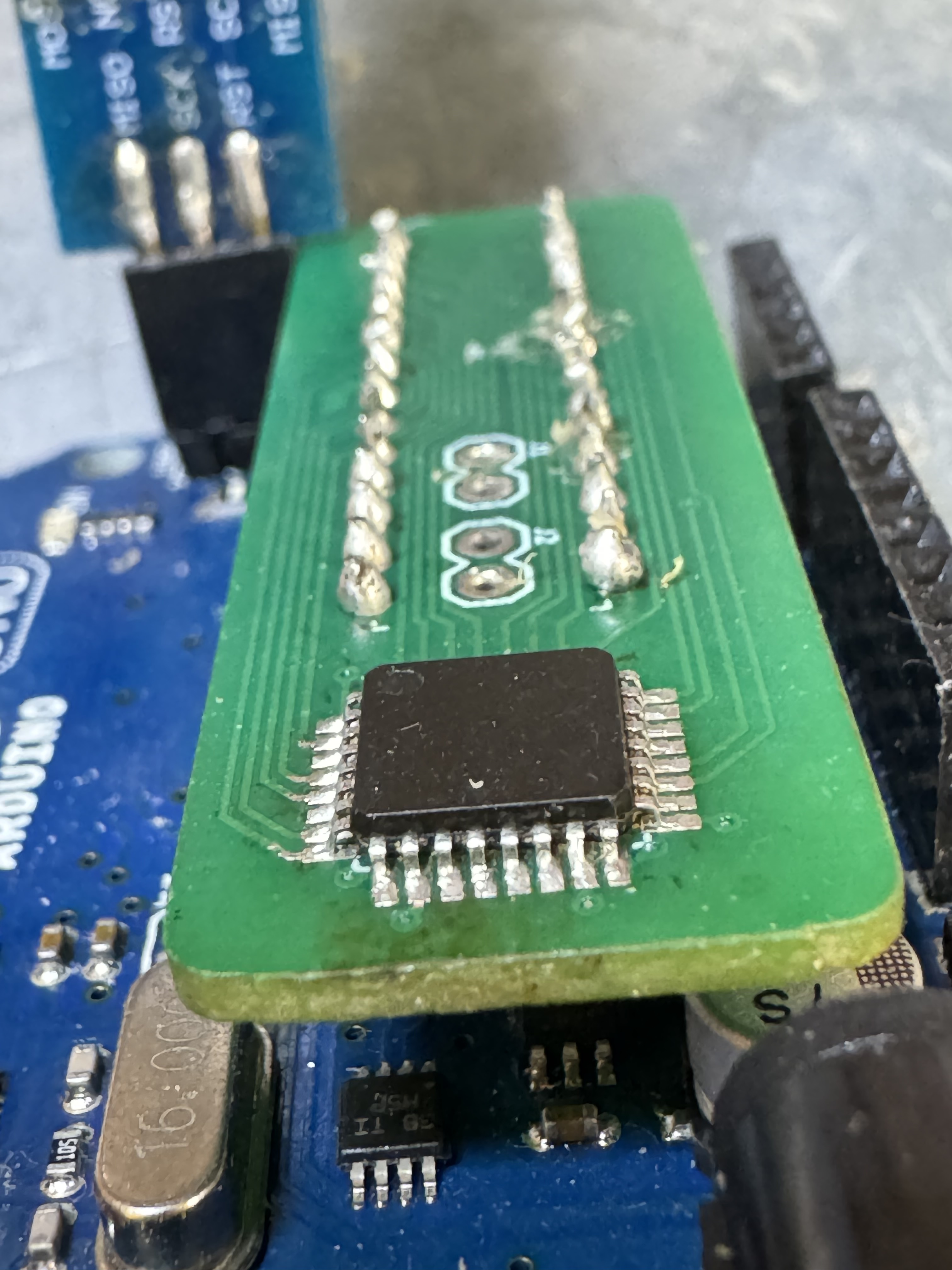
• I decided to desolder the chip from the tester and place it on a breakout board.
• I then tried to flash it externally via USBasp and avrdude.
• Still getting the same error:
program enable: target does not answer (0x01)
I also tried using -B 125 to slow down the SCK clock speed, but still no luck.
At this point, I’m wondering if:
1. The fuse bits were set to use an external clock, and the chip is now unresponsive due to a missing clock signal.
2. The microcontroller is not an ATmega328P at all.
3. Or possibly the chip is permanently damaged.
Any suggestions? Is it possible pin 25 being tied to GND indicates a different chip, or does it still sound like a fuse issue?
I happen to have the exact same chinese aliex tester. I don't know much about Arduinos and stuff, so I wanted to find an instruction how to change the firmware. Because I can't even recalibrate the capacitance settings... Well, you probably have the same firmware, so you know. Right, so I don't know much about programming, but I can use a continuity tester. And here's what's strange. Everything you said checks out. So the 1st hole goes to 18th pin, the second - to the 21st pin, the reset (why no pin number? it's 29 on mine) - and so on. BUT
when I check it, it shows me the voltage drop, the usual 0.6v (0.57v to be precise with inverted voltage, so black probe on a pin) and 1,087v the other way around (black probe on the ground), so I think your chip is cooked or you forgot to disconnect something. Just to be sure I checked it on my Arduino and it shows very similar numbers
Sorry, I couldn’t check properly earlier. I measured these pins as continuity, but after soldering the IC in place, I checked again and now the connection is detected as the 29 (reset) pin. Additionally, I’m getting the error shown on the screen (as in the picture). The 25th pin is still reading as a GND connection. When I test in diode mode, I measure a 0.019V voltage drop.Also, the 9V battery should be working fine.