Looking for some advice on what I am missing. I am a software dev, so my electronics skills are a bit weak and have likely missed something basic
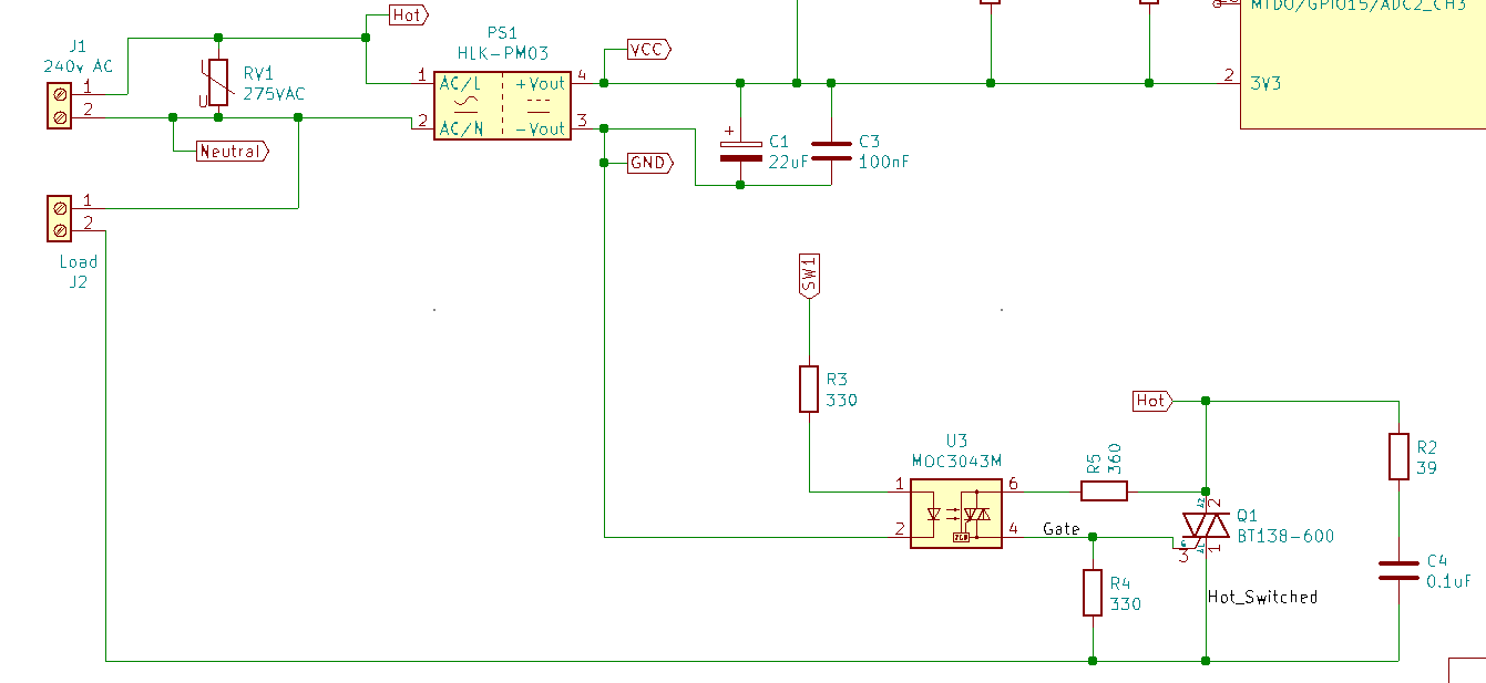
I have an application of a MOC3043 and a BT138-600 triac connected to an ESP32. I have used this circuit multiple times without problems controlling loads (at 240VAC and < 100 Watt).
As the BT138-600 datasheet indicates it can switch 12A (at RMS and 95A peak) I decided to try controlling a heating unit (again the datasheet suggests this is a typical application for the triac). The unit contains two elements which can be turned on/off independently of each other, one at 65 Ohms and the other at 55 Ohms. On connecting the unit to the triac circuit with both elements turned on, the MCU was able to successfully turn the heater on. However, it was unable to turn the heater off. After approx 10 seconds the triac let out smoke and the case cracked - maybe it short circuited inside but the fuse (10A) did not blow.
I decided to replace the triac and try again with individual elements. In which case I was able to turn the smaller heater element on/off (at approx 800 Watt). However, the larger one was not able to be turned off and I manually turned it off before the triac was damaged again. The second element is well within the triac specification as I understand it.
I suppose this suggests there was still current flowing through the circuit and the triac was unable to turn it off. But this is about the limit of my understanding.
The snubber circuit involves X2 capacitor and 2 W resistor. I am not sure if I need to tweak the snubber - but I am using standard values from the MOC3043 datasheet and the load is resistive (whereas I though the snubber was only needed for inductive/capacitive loads).
Also, I have deviated from the diagram above by using 470 Ohms on R5 - but this should be fine as 360 Ohms is a minimum used for protecting the MOC. More info about this is here: https://www.uploadarchief.net/files/download/gate_r.pdf
R3 is on the low voltage side of the MOC and triggers without issue. The issue is when SW1 goes low after being high the triac does not turn off with > 1kW load. I could understand trying a lower R3 if the MOC was not turning the triac on.
Your circuit looks good, thanks for the schematic! Try 220 Ohm resistor for R4, that may help and also you med to work on the snubber as you're probably getting some induction in the external wiring. If you can put a scope on it that would help a lot but if you do not have experience with mains and scopes this would be a bad time to learn. Be sure pins 1 and 2 are not reversed, if so it could cause false triggering.
Hi,
actually the snubber is recommended for inductive loads, but it doesn't get in the way with resistive loads.
In my Triac projects I never used this configuration that includes this 330 Ohm resistor R4.
I suggest removing it and testing your project again.
You probably need a heatsink (or a bigger heatsink). The datasheet shows current handling capability dropping drastically as the case temperature goes over 90 degrees C. And of course the situation is worse if the TRIAC is exposed to the heat from the heating element.
That's not unusual... The main purpose of a fuse is to prevent a fire or further damage after something has gone wrong. Most semiconductors short-out when they die or burn-up whereas a fuse blows open, stopping current flow. In this case, a blown-shorted TRAIC doesn't cause excess current. The current is limited by the load and it just won't turn off.
Thanks for the suggestion. Before I remove it, I need to better understand why the datasheet puts it there Maybe you were using a different triac driver?
R4 is to increase dV/dt immunity of the triac (prevent false switch on at fast increase of voltage). Maybe it also helps for turn off.
To the thermal hypothesis: did you try to turn off the heater after a few mains cycles (say 40 ms)? The triac should still have low temperature and be able to turn off.
You don't need a current probe. Just inline a small resistor and use a voltage probe. Also voltage at the triac terminals is important. Are there some spikes? Is there some difference between the heaters in shape of the waveform?
Load resistance = 65 * 55/(65+55) =29.79 ohms
Current = 240v / 29.76 = 8.064A
current dissipated in triac = 1 * 8.06 = 8.06watts;
Thermal without heatsink is 60 deg C / watt
At a load 8 watts amd 60 deg C /watt = 8 * 60= 480 degrees C rise in temperature above ambient.
This temperature is well above the temperatures capability of the device.
Good idea. I have just tried this. Turned triac on for one full cycle/sine wave per second. It was able to control the load. So must be a heat sink issue
Thanks for the help in the calculation - much appreciated. If I am reading the datasheet for the triac correctly it might be even worse at approx 11 Watt dissipation for 180 degree conduction at 8 A.
Looking at the heat sink used, its is likely rated at about 2 or 3 Watt. So this is no doubt the issue and will probably let me control loads up to almost 2 A.