Hello!
I am trying to design a setup that uses a stepper motor and lead screw to move a linear bearing back and forth according to the input of a three-way switch, but I have been encountering problems with wiring in the switch.
I am using an Arduino Uno and Sparkfun's EasyDriver stepper motor controller to control the stepper motor itself.
I wish I could explain in detail what is going wrong, but I really can't get any sort of consistency. It will work how I want it to one minute, and then just start randomly running the motor and stopping the next.
What I'm trying to do with the switch is have it so that when it is flipped left it will rotate the motor one way, when it's flipped right it will rotate it the other way, and when it's in the middle it will stop. I already know that there's going to be something wrong with stopping the motor, but I can't even get it to work correctly when flipping the switch left or right to find out where that problem will be.
I have some proficiency with programming in general (I'm much more familiar with Java than I am with any other language at the moment), but I don't have much experience with circuitry, so I fear that is where my problem may be.
Here's my code:
#include "Arduino.h"

const int posA = 4;     // Position A pin
const int posB = 5;     // Position B pin

int dirpin = 2;
int steppin = 3;


void setup()
{
// set posA as input
pinMode(posA, INPUT);
// set posB as input
pinMode(posB, INPUT);
pinMode(dirpin, OUTPUT);
pinMode(steppin, OUTPUT);
Serial.begin(9600);
}
void loop()
{
int stateA = digitalRead(posA);     // variables for reading the switches status
int stateB = digitalRead(posB);
  if(stateA == HIGH){
    digitalWrite(dirpin, LOW);
    digitalWrite(steppin, LOW);
    digitalWrite(steppin, HIGH);
    delayMicroseconds(500);
  }

  else if(stateB == HIGH){
    digitalWrite(dirpin, HIGH);
    digitalWrite(steppin, LOW);
    digitalWrite(steppin, HIGH);
    delayMicroseconds(500);
  }
  else if (stateA == LOW && stateB == LOW){
    digitalWrite(dirpin, LOW);
    digitalWrite(steppin, LOW);
  }
}
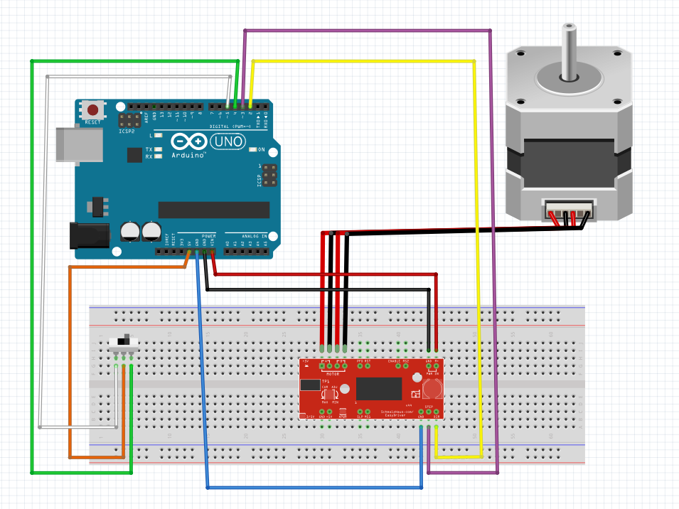
Attached is a picture of how everything is wired up:
Any help is appreciated. Thanks!