Hi everyone.
I'm posting this plea for help after a few weeks of researching and trying to figure out the best solution.
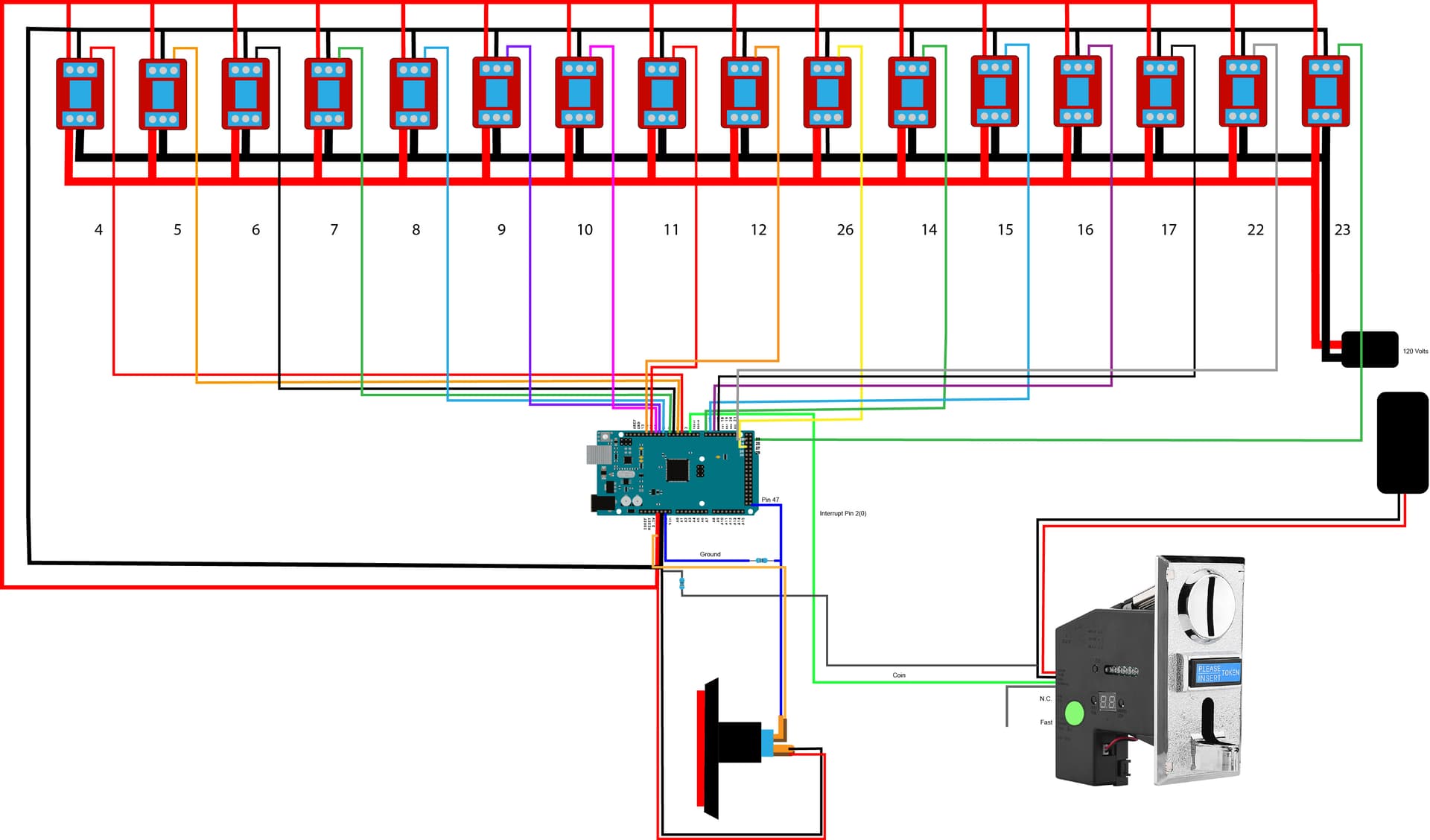
I'm creating an interactive boardwalk game, and I'm having trouble with false interrupt pulses being detected from the coin acceptor, but mainly only when the 120V circuit is connected.
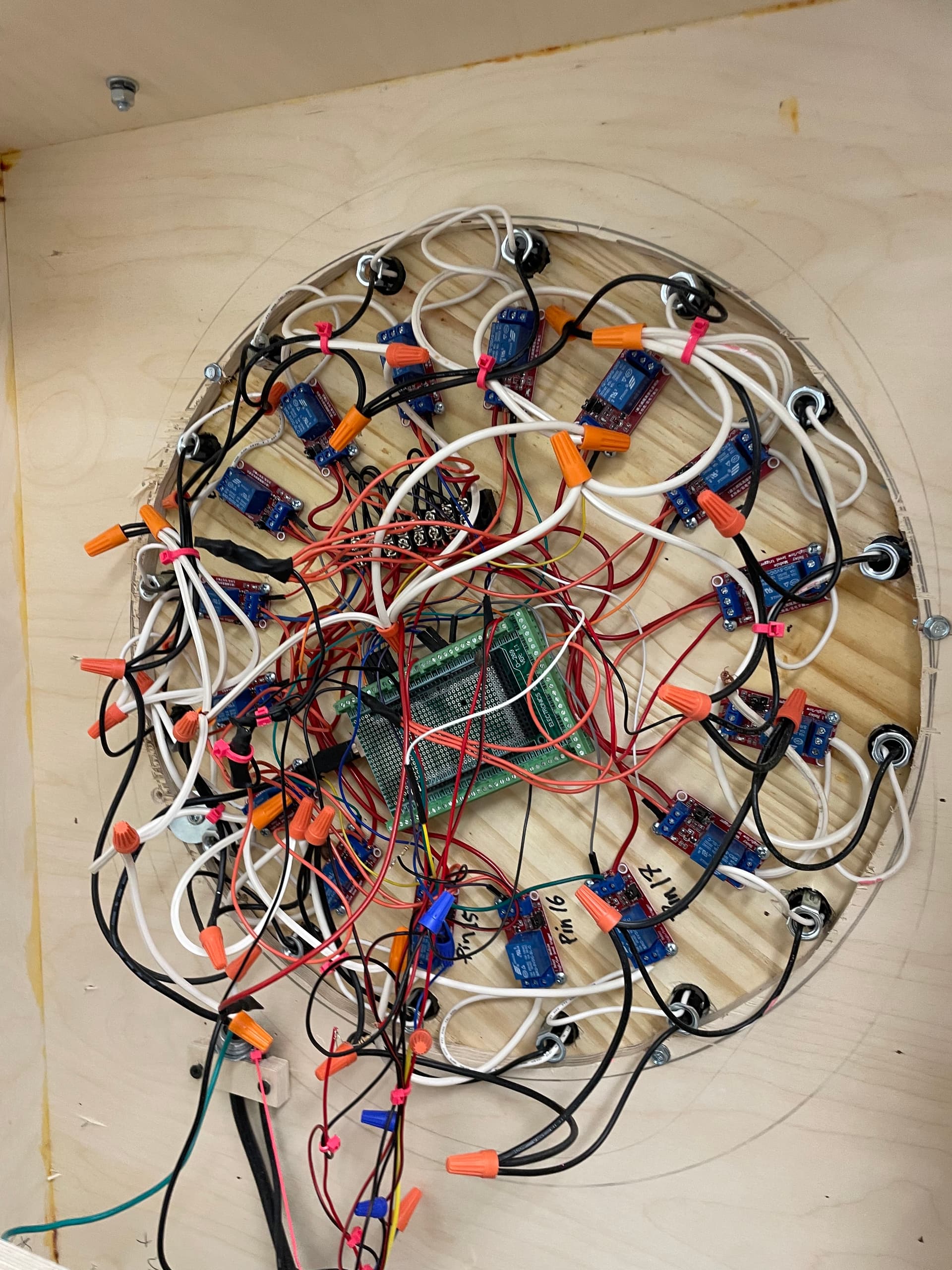
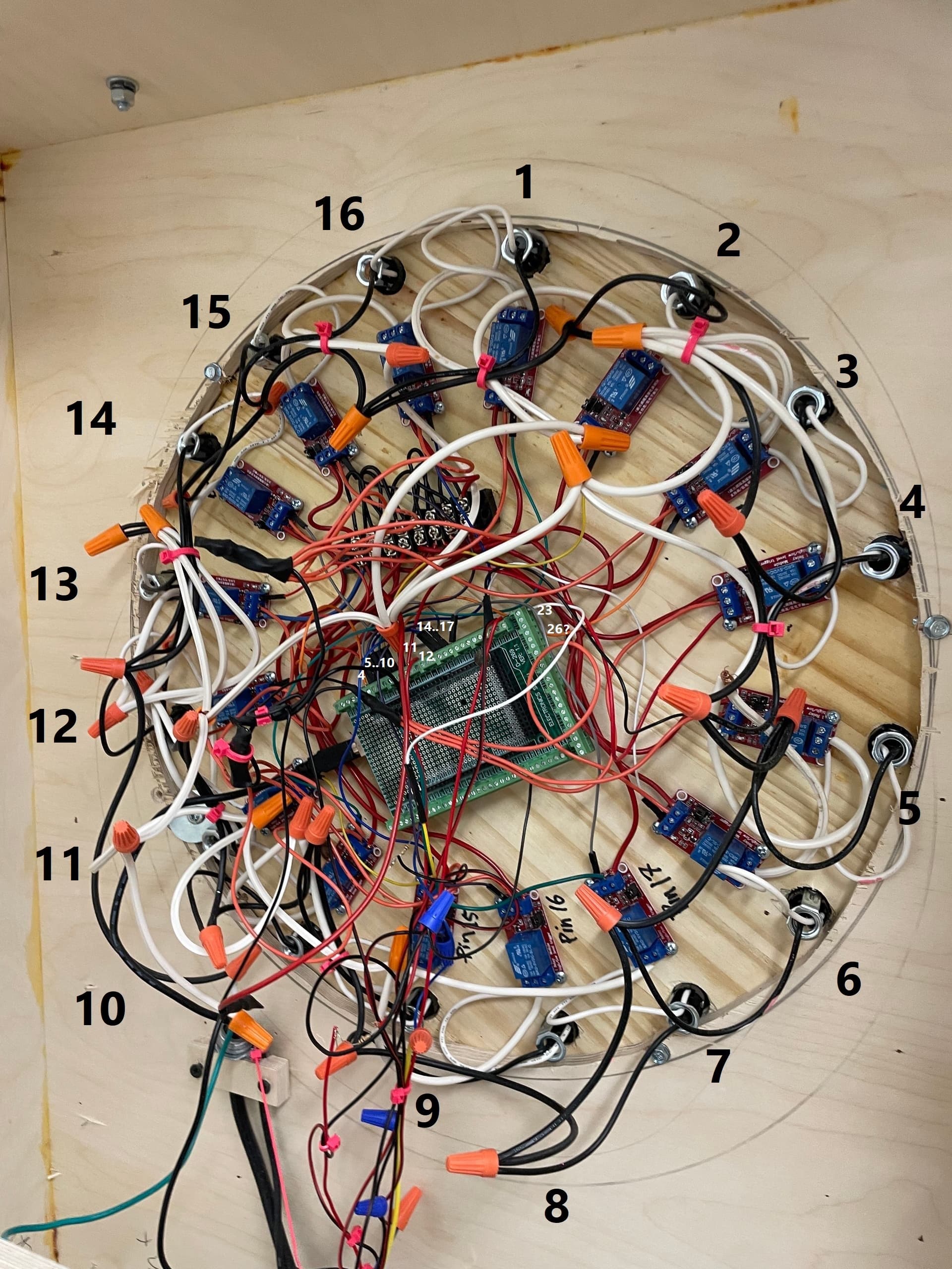
I have 16 one-channel relays daisy chained in a circle, an Adafruit coin acceptor, and a lighted button.
Here are some examples of the false interrupts I have been experiencing:
- When a coin is touched to the metal plate of the coin acceptor, but not inserted. (I as sume this is a grounding issue?"
- When the bell rings, powered by 5V 1amp, not shown in the diagram.
- When I move the machine while it is on.
I tried doing a pullup resistor with the coin acceptor which didn't work, but a pulldown resister seems to work okay.
I've perused the internet and this forum for possible solutions and the following solutions are:
- Ceramic capacitors across the signal wire
- Wire shields
- Ferrite
- Twisted wires
Code:
#include <Arduino.h>
#include <elapsedMillis.h>

// Module connection pins (Digital Pins)
#define CLK 3
#define DIO 4

volatile int impulsCount = 0;
// Led initialization
volatile int Leds = 16;
volatile int led[] = { 4, 5, 6, 7, 8, 9, 10, 11, 12, 26, 14, 15, 16, 17, 22, 23 };

const int Button_Pin = 25;
const int Led_Pin = 47;
const int Bell_Pin = 50;
volatile int i = 0;

// For Timer
elapsedMillis timeElapsed;

//*************************** Void Setup *******************************************//
void setup() {
  Serial.begin(9600);

  pinMode(2, INPUT);
  pinMode(Bell_Pin, OUTPUT);

  attachInterrupt(0, incomingImpuls, FALLING);
  Serial.println("................Setup Started");

  pinMode(LED_BUILTIN, OUTPUT);  // For Test purpose onboard Led is being used as button Led
  pinMode(Button_Pin, INPUT);
  pinMode(Led_Pin, OUTPUT);

  digitalWrite(LED_BUILTIN, HIGH);
  digitalWrite(Led_Pin, HIGH);
  Serial.println("[Button LED ON]");
  digitalWrite(33, LOW);

  for (i = 0; i <= Leds; i++) {
    pinMode(led[i], OUTPUT);
  }

  Serial.println(".................Setup Completed");
  Serial.println(impulsCount);
}
//********************************** Start ********************************//
void Start_Pattern() {
  Serial.println("Startup: All 16 Leds will light Up for 5 seconds");
  impulsCount = 0;

  for (i = 0; i <= Leds; i++) {
    digitalWrite(led[i], HIGH);
  }
  delay(0);
  for (i = 0; i <= Leds; i++) {
    digitalWrite(led[i], LOW);
  }
  Serial.println("Startup Completed");

  impulsCount = 0;
}

//*************************** 1 Minute and 80 ms Pattern *****************//
void Pattern1() {
  impulsCount = 0;
  Serial.println("Pattern 1: All Leds will blink in circle for 1 minute");
  Serial.println(impulsCount);
  timeElapsed = 0;
  unsigned int interval = 3000;
  while (timeElapsed < interval) {
    for (i = 0; i <= Leds; i++) {
      digitalWrite(led[i], HIGH);
      delay(180);
      digitalWrite(led[i], LOW);
    }
  }
  Serial.println(impulsCount);
  Serial.println("Pattern 1 Completed");
}

//******************** 30 seconds Random Blink Pattern *****************//
void Pattern2() {
  Serial.println("Pattern 2: Random Leds will blink for 30 seconds");
  timeElapsed = 0;
  unsigned int interval = 3000;
  while (timeElapsed < interval) {
    int temp = random(16);
    digitalWrite(led[temp], HIGH);
    delay(180);
    digitalWrite(led[temp], LOW);
  }
  Serial.println("Pattern 2 Completed");
  Serial.println("Pattern 1 & 2 will be repeated ");
}

//***************************** Interrupt Code  **************************//
void incomingImpuls() {
  impulsCount = 1;

  Serial.println("coin");

  for (i = 0; i <= Leds; i++) {
    digitalWrite(led[i], LOW);
  }

  while (digitalRead(Button_Pin) == LOW) {
    digitalWrite(LED_BUILTIN, LOW);
    digitalWrite(Led_Pin, LOW);
    delay(100000);
    digitalWrite(LED_BUILTIN, HIGH);
    digitalWrite(Led_Pin, HIGH);
    delay(100000);
  }

  Button_Pattern();
}
//*************************** After Button Pressed pattern *****************//
void Button_Pattern() {
  int timer = 500;
  int temp = 500;
  for (int k = 0; k < 4; k++) {
    for (i = 0; i <= Leds; i++) {
      digitalWrite(led[i], HIGH);
      delay(timer);
      timer = timer + temp;
      Serial.println(timer);
      digitalWrite(led[i], LOW);
      if (timer == 1900 && i == 11) {
        digitalWrite(led[11], HIGH);
        i = 20;
      }
    }
    temp = temp + 100;
  }
  for (i = 0; i <= Leds; i++) {
    digitalWrite(led[i], LOW);
    digitalWrite(Bell_Pin, HIGH);
  }
  for (i = 0; i < 10; i++) {
    digitalWrite(led[0], HIGH);

    Serial.println("11 BLINK ON");
    delay(80000);
    digitalWrite(led[0], LOW);

    Serial.println("11 BLINK OFF");
    delay(80000);
  }
  digitalWrite(Bell_Pin, LOW);
  impulsCount = 0;
}

void loop() {
  Serial.println(".....................................Loop Started");
  Start_Pattern();
  Pattern1();
  Pattern2();
}
Thank you for your help in advance. I'd really like to solve this issue. ![]()


