I am working on a weather station project with the intention of using two nRF24 modules to connect an Arduino Uno to a Uno WIFI Rev2 which then uploads the data to weather underground once its inside. The only part of this project that I can not get working is the transceivers. I've bought two pairs of these now and adapter boards, used shorter wires, tried all the codes available online and the best I have got is occasional random values from the receiver in the serial monitor.
Even when not using the Uno WIFI the same thing happens.
This is one particular code that ChatGPT wrote. The transmitter appears to work fine, but nothing is displayed in the receiver code. The RF24 library is installed on both devices.
// Transmitter code by ChatGPT
#include <SPI.h>
#include <nRF24L01.h>
#include <RF24.h>

RF24 radio(9, 8);  // CE, CSN pins

void setup() {
  Serial.begin(9600);
  radio.begin();
  radio.openWritingPipe(0xF0F0F0F0E1LL);  // Set the pipe address for communication
  radio.setPALevel(RF24_PA_HIGH);        // Set the power level
}

void loop() {
  const char *message = "Hello, receiver!"; // Message to send
  radio.write(message, strlen(message));   // Send the message
  Serial.println("Message sent: " + String(message));
  delay(1000);  // Wait before sending the next message
}
// Reciever code by ChatGPT
#include <SPI.h>
#include <nRF24L01.h>
#include <RF24.h>

RF24 radio(9, 8);  // CE, CSN pins

void setup() {
  Serial.begin(9600);
  radio.begin();
  radio.openReadingPipe(1, 0xF0F0F0F0E1LL); // Set the same pipe address as the transmitter
  radio.setPALevel(RF24_PA_HIGH);           // Set the power level
  radio.startListening();                  // Start listening for incoming messages
}

void loop() {
  if (radio.available()) {
    char message[32] = "";
    radio.read(&message, sizeof(message)); // Read the incoming message
    Serial.println("Received: " + String(message));
  }
}

Is having all the wires overlapping causing issues? When these are active the have been from 30cm to 1m apart with no change (although sometimes the outputs from the receiver change in frequency based on where I am standing near).
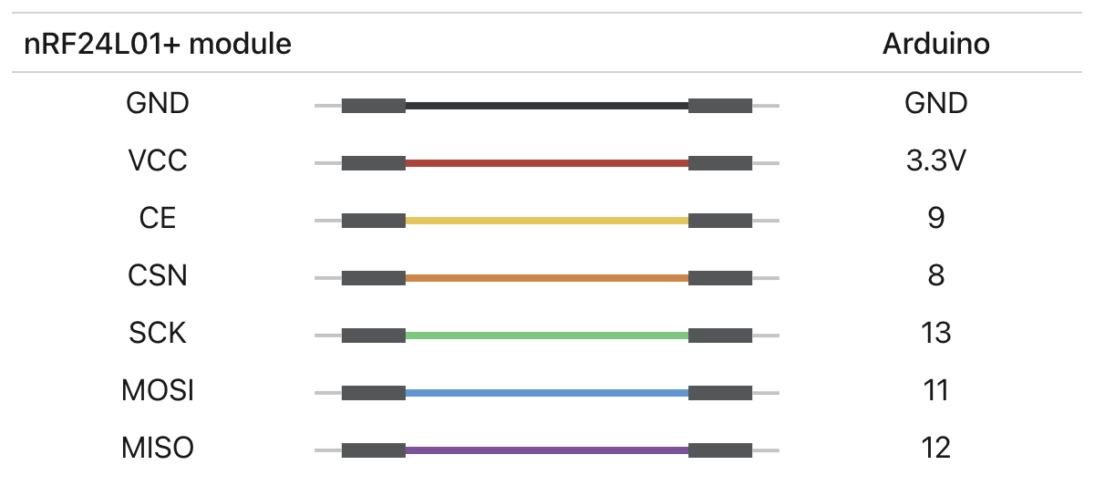
I have used the wiring suggestions from Last Minute Engineers
As evident I have also soldered a 10uF capacitor on the ground and vcc pins of each transceiver. I am both hoping and assuming that the modules work.
What should I do to make these work? I have heard about wrapping ground wires around some of the wires but am not sure which ones or how to do that. Any help would be greatly appreciatedd
