Hello, I'm fighting with reading data through UART, which is not as expected.
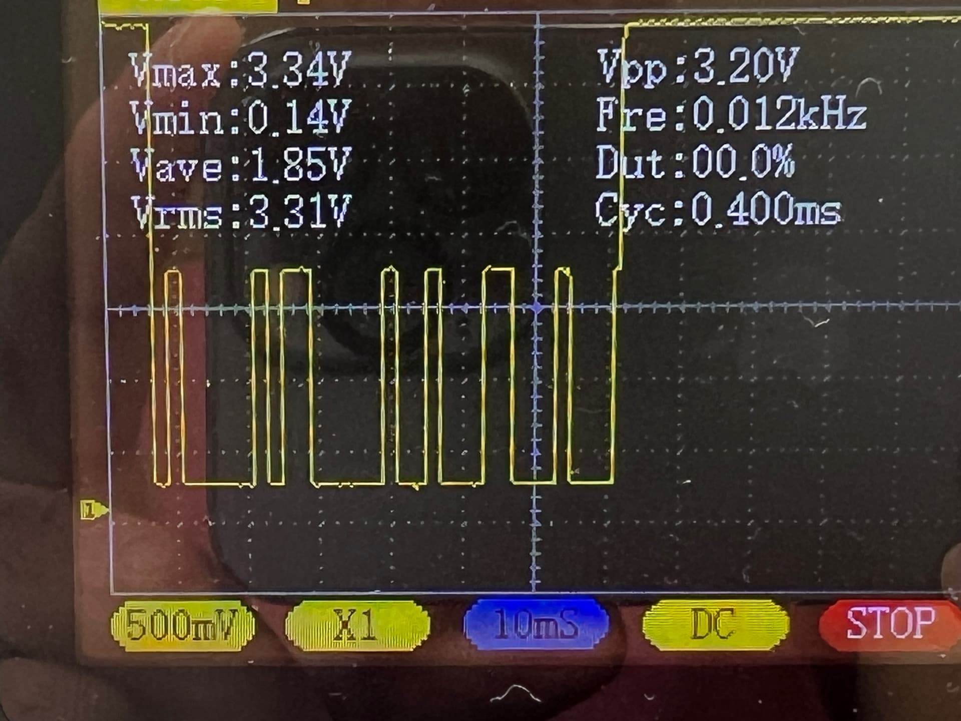
I have a signal as in the attached image. The waveform is taken from PIN 13, UART RX.
The device in question is a SSS-Siedle door system with video camera and the signal comes from the Ta/Tb In-Home serial bus.
I admit I don't have the precise baud rate and I've been trying with all possible values which give a kind of possible result.
Looking at the waveform I should read a 30-33 bit long data, but I always get a 8 bit data.
I'm using the Serial1.read() at the moment and the funny thing is that I get two different data readings for the same kind of action: 240 and 248 (for doorbell ringing) and 128 and 192 (for door opening) using a 74880 baud rate.
In fact I cannot rely on the readings at all.
I've been trying with the rate of 19200 as pointed out from different forums, but it seems the best result until now is actually 74880. Looking at the oscilloscope the baud rate could be around 15000 but using it I don't get any reading at all.
Am I doing something wrong? Yes I am, but how to get a correct reading from the UART?
Thanks a lot in advance
You don't mention how you are getting the signal from Ta/Tb into your MKR Zero UART. Have you wired directly to your Arduino Rx pin?
It's very unlikely that a direct connection is required and much more likely that you need an interface board for RS232 or RS422 or RS485. Your user guide should provide some details unless the manufacturer wants to hide that information in the hope that the purchaser sticks with their product suite.
Without looking further, I wonder if the fact that the connections are labelled Ta & Tb might suggest that the serial interface is RS485? That would make sense for long range wired comms.
EDIT: Ah, looking at the diagram it's clearer now.....
It's true, it's necessary not only the rx data part but also an optocoupler in order to keep electric insulation. As for the resistors and the transistor I've preferred other values and another configuration.
No, the signal is adapted and transformed mainly because Ta/Tb is a carrier around 28 V and modulated for the video camera and audio too.
Anyway, despite the brand and product, the waveform is pretty clear and the board should read all the 30 bits as it starts with a start bit and I can really count the 30 bits, almost. The main question is how to make Arduino read the correct data.
Looking at the waveform from the oscilloscope, it seems the data word is 1000010110000100100011001000 in that case, much larger than what I get, which is always an 8 bit word.
So the question is what is the cause for stopping reading the whole word.
I admit I have not tried the functions readBytes() and readBytesUntil(). I can imagine the function read() returns all the available data.
My serial comms knowledge is slowly evaporating due to under use, but if it were 15000 bits/sec, then wouldn't the 30 or so bits would take around 30/15000 seconds = about 2ms. Unless I'm reading it wrong, the scope trace appears to show a message taking roughly 64ms.
Another thought, Is the amplitude of the waveform meeting the voltage requirements for the SAMD21 UART to correctly detect 1s and 0s?
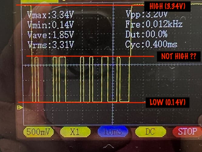
True, it might be an issue with the detection. I've put high precision trimmers in order to adjust both the input signal sensitivity and the pull-up for the UART RX.
Let me play a bit more with these. I'll post the result in any case
Here is a better waveform, result of adjusting some resistors. It's not perfect but I presume it's okay for the RX - I hope a Schmitt trigger won't be necessary! I'll try more in the next days.
The communication Baud rate for the built-in USART will be mentioned in the data sheet for your processor. It will be a function of the processor clock frequency and only certain, specific Baud rates will work. Picking some random value will never work.
And now it looks quite good according to the attached image, I would say.
But the issue still remains.True @Paul_KD7HB, it's a challenge to make it work properly as the suggested baud rate of 19200 doesn't seem to have success.
Thanks @markd833, unfortunately the oscilloscope is not really professional and it does not have that function. I'm trying manually - I hope I will succeed anyway