Hi everyone,
I'm trying to get UART communication working between an Arduino and a TMC2209 stepper driver, but I can't seem to make it work.
Here’s how I’ve connected the pins:
- PDN_UART is connected directly to Arduino RX (pin 5), and to TX (pin 6) through a 1k resistor
- EN -> pin 7
- STEP -> pin 4
- DIR -> pin 3
- MS1 and MS2 are left unconnected
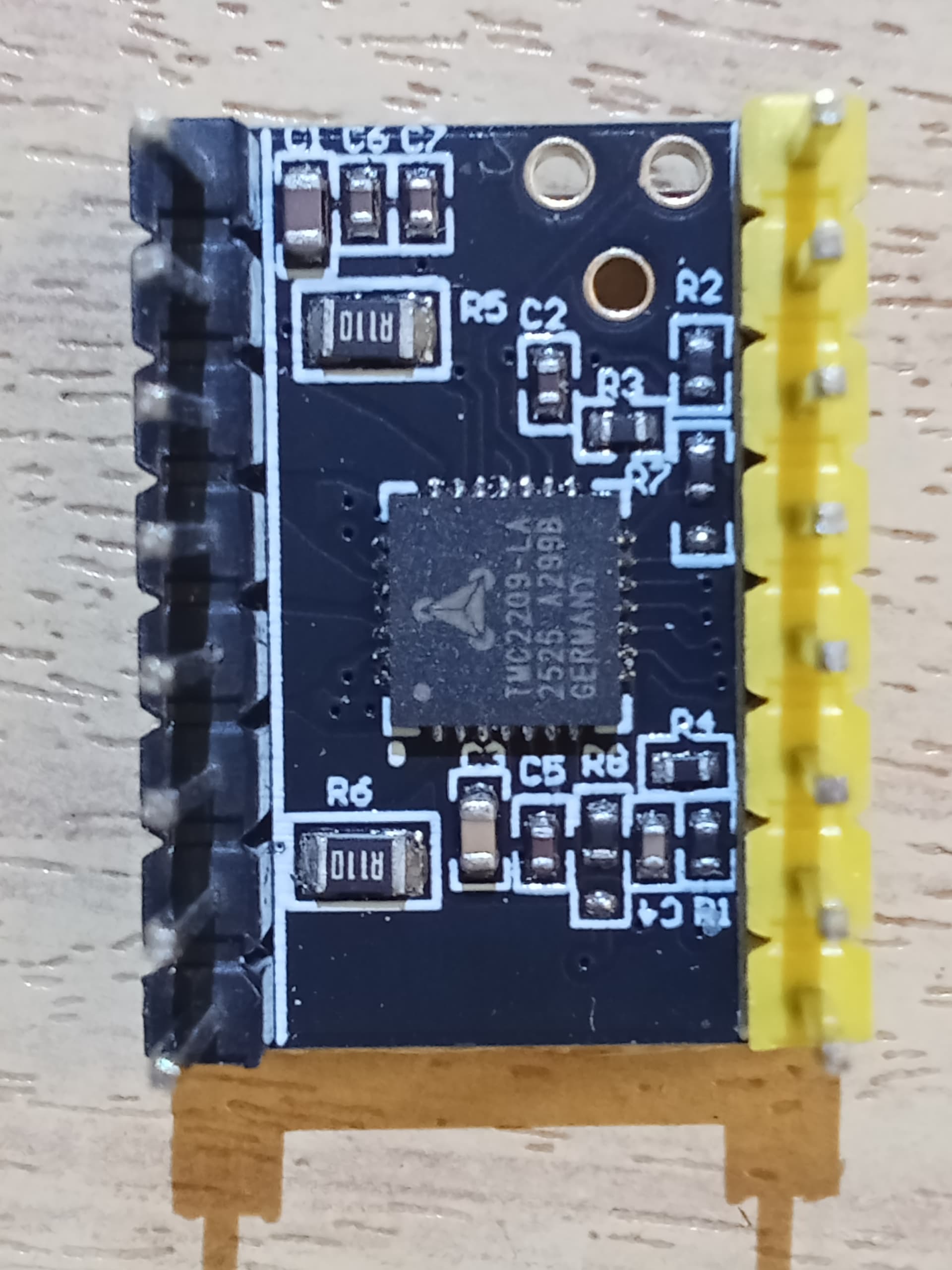
I'm starting to suspect the issue might be with the driver module itself. So first, I’m attaching a couple of photos of the module, including a close-up of the PDN_UART pin under a microscope:
photos:


Below is the code I’m currently using. In this setup, I’m working with a custom PCB that has the driver soldered directly on it, along with an OLED screen and an ATmega328P.
Sorry if the code seems a bit messy — I’ve split it across several files to try and keep things organized.
main.ino:
#include <TMCStepper.h>
#include <Wire.h>
#include <Adafruit_SSD1306.h>
#include <SoftwareSerial.h>

// altre schede
#include "oled_display.h"
#include "motor_control.h"
#include "config.h"


#define TMC_RX_PIN    6 // Arduino TX -> TMC RX    (tramite resistenza 1Kohm)
#define TMC_TX_PIN    5 // Arduino RX <- TMC TX

// OLED
#define SCREEN_WIDTH 128
#define SCREEN_HEIGHT 64
#define OLED_RESET   -1


// Setup SoftwareSerial (Rx, Tx)
SoftwareSerial tmcs(TMC_TX_PIN, TMC_RX_PIN); // RX, TX

#define R_SENSE 0.11f

TMC2209Stepper driver(&tmcs, R_SENSE, 0x00);  // Aggiunto indirizzo 0x00


void setup() {

  pinMode(EN_PIN, OUTPUT);
  pinMode(STEP_PIN, OUTPUT);
  pinMode(DIR_PIN, OUTPUT);
  pinMode(BUTTON_PIN, INPUT_PULLUP);
  pinMode(LED_PIN, OUTPUT);
  pinMode(TMC_RX_PIN, INPUT);
  pinMode(TMC_TX_PIN, OUTPUT);


  digitalWrite(EN_PIN, LOW); // Enable driver

  // OLED init
   setupOLED();  // Inizializza il display una sola volta

  // Setup SoftwareSerial UART a 115200
  tmcs.begin(19200); // test 19200 prima di tornare a 115200
  delay(100);

  driver.begin();
  driver.toff(5);
  driver.rms_current(600);
  driver.en_spreadCycle(false);
  driver.pwm_autoscale(true);
  driver.microsteps(1);


}

unsigned long currentMillis;
unsigned long previousMillis = 0;
unsigned long oledPreviousMillis = 0; //--
const long interval = 500; // 500 ms led lampeggiante
bool ledState = false;
bool buttonPressed = false;

void loop() {
  currentMillis = millis();

  // LED blink
  if (currentMillis - previousMillis >= interval) {
    previousMillis = currentMillis;
    ledState = !ledState;
    digitalWrite(LED_PIN, ledState);
  }

  // Aggiorna display
  if (currentMillis - oledPreviousMillis >= 300) {
    oledPreviousMillis = currentMillis;
    driver.microsteps(1);
    uint16_t currentMicrosteps = driver.microsteps(); // LEGGE valore dal driver
    updateOLED(currentMicrosteps);
  }

  // Pulsante
  if (digitalRead(BUTTON_PIN) == LOW && !buttonPressed) {
    buttonPressed = true;
    startMoveSteps(NUM_STEPS);
  }

  if (digitalRead(BUTTON_PIN) == HIGH) {
    buttonPressed = false;
  }

  // Gestione motore
  updateMotor();
}
config.h:
#ifndef CONFIG_H
#define CONFIG_H


// Pin
#define EN_PIN        7
#define STEP_PIN      4
#define DIR_PIN       3
#define BUTTON_PIN    9
#define LED_PIN       2
#define NUM_STEPS    2048
#define TMC_TX_PIN    5

#endif
motor_control.cpp:
#include <Arduino.h>
#include "motor_control.h"
#include "config.h"

static int stepsToDo = 0;
static int stepsDone = 0;
static unsigned long lastStepTime = 0;
static const unsigned int stepDelayMicros = 1000; // 1ms per passo
static bool motorMoving = false;

void startMoveSteps(int steps) {
  stepsToDo = steps;
  stepsDone = 0;
  lastStepTime = micros();
  motorMoving = true;
}

void updateMotor() {
  if (!motorMoving) return;

  unsigned long now = micros();

  if (now - lastStepTime >= stepDelayMicros) {
    lastStepTime = now;

    // Un impulso
    digitalWrite(STEP_PIN, HIGH);
    delayMicroseconds(5); // breve HIGH per segnale valido
    digitalWrite(STEP_PIN, LOW);

    stepsDone++;
    if (stepsDone >= stepsToDo) {
      motorMoving = false;
    }
  }
}

bool isMotorMoving() {
  return motorMoving;
}
motor_control.h:
#ifndef MOTOR_CONTROL_H
#define MOTOR_CONTROL_H

void startMoveSteps(int steps);
void updateMotor();

bool isMotorMoving(); //

#endif
oled_display.cpp:
#include "oled_display.h"
#include "config.h"
#include <Adafruit_GFX.h>
#include <Adafruit_SSD1306.h>
#include <Wire.h>

// Config display
#define SCREEN_WIDTH 128
#define SCREEN_HEIGHT 64
#define OLED_RESET    -1
#define OLED_ADDRESS  0x3C

Adafruit_SSD1306 display(SCREEN_WIDTH, SCREEN_HEIGHT, &Wire, OLED_RESET);

void setupOLED() {
  if (!display.begin(SSD1306_SWITCHCAPVCC, OLED_ADDRESS)) {
    Serial.println("ERRORE OLED!");
    return;
  }
  display.clearDisplay();
  display.setTextSize(2);
  display.setTextColor(SSD1306_WHITE);
  display.setCursor(0, 0);
  display.println("OLED OK");
  display.display();
}

void updateOLED(uint16_t microsteps) {
  display.clearDisplay();
  display.setTextSize(2);
  display.setTextColor(SSD1306_WHITE);
  display.setCursor(0, 0);
  display.print("Microsteps:");
  display.setCursor(0, 30);
  display.print(microsteps);
  display.display();
}
oled_display.h:
#ifndef OLED_DISPLAY_H
#define OLED_DISPLAY_H

#include <Arduino.h>
#include <Adafruit_SSD1306.h>

extern Adafruit_SSD1306 display;

void setupOLED();
void updateOLED(uint16_t microsteps);

#endif
Any help or suggestions would be greatly appreciated. Thanks in advance!

