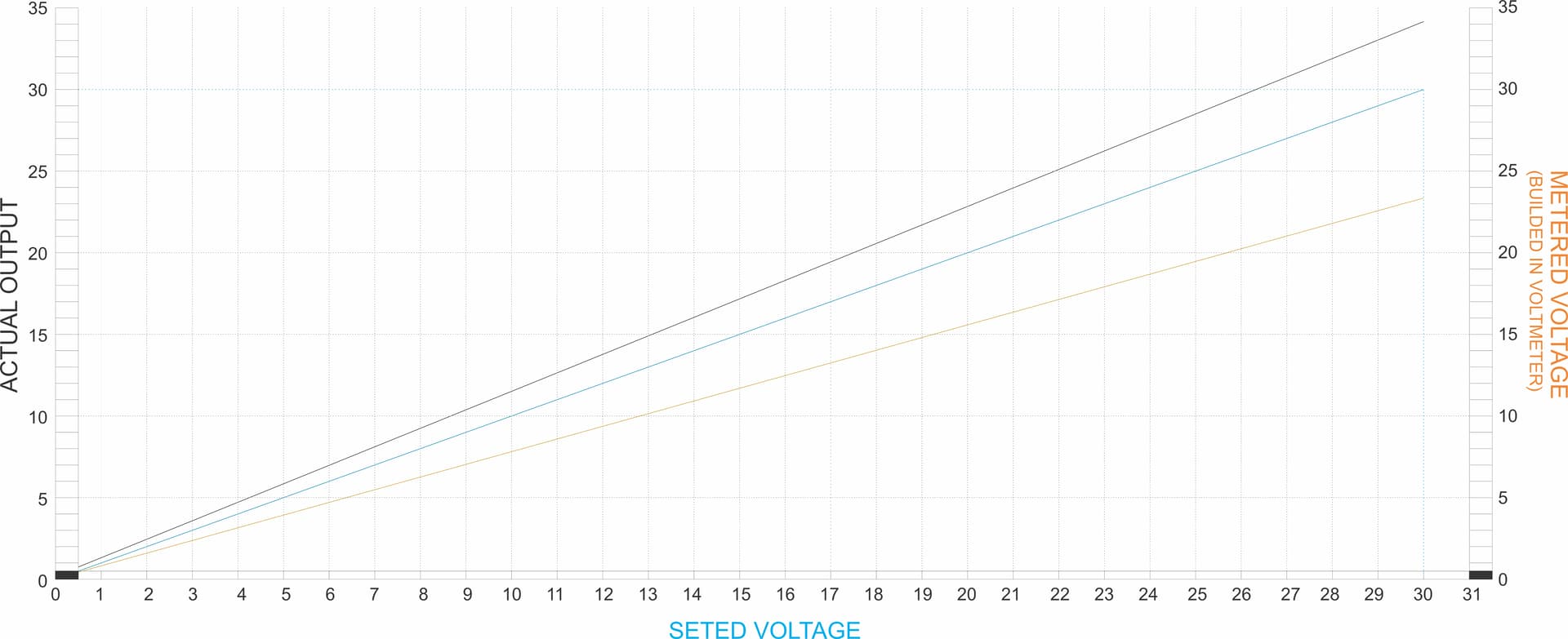
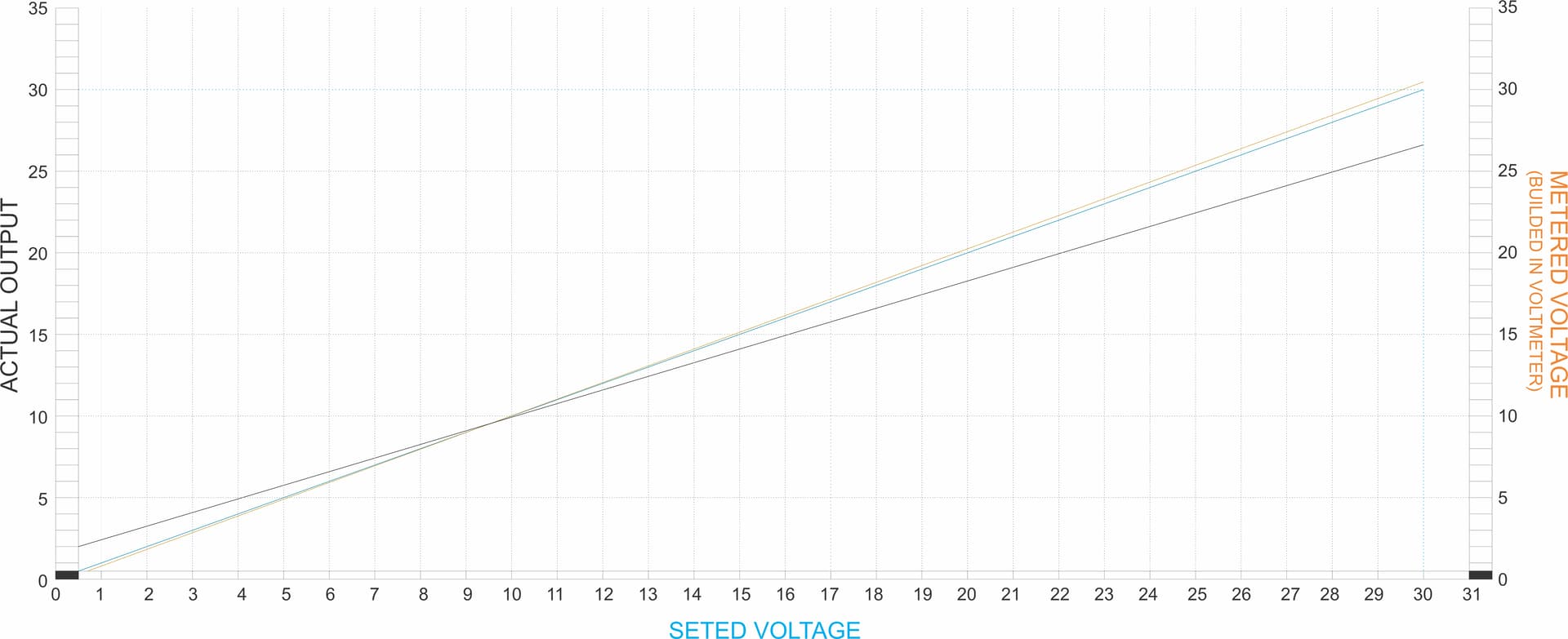
There is a problem with the "set voltage", "output voltage (builded in voltmeter)" and "actual output"... just cannot make coincide the tree values at same time, minimum mismatch in values are 2.85V can only match, (Seted value & actual output) or (output measured voltage (builded in voltmeter) & actual output)...
If you have a good VOM, that is the correct voltage. The display is a gimmick.
Thanks, but the standalone use is tricky...
Perhaps I am misunderstanding something. Can you explain better, show pictures, or a diagram?

Sorry, I still don't understand. Is there an Arduino or similar involved? Show us the wiring diagram and the code in code tags.
Are you loading the output with anything ?
Ok, now I understand. I still recommend post 2.
No, just measuring with Multimeter, and if the "seted output current" is even slightly over the drained current, the voltage didn't drop...
What does the manual say about calibration? It likely specifies a minimum load, acceptable voltage tolerance, and the reference set points, along with instructions on what to adjust. Your schematic should clearly indicate all of these calibration points.
Also, is your multimeter at least a 4.5-digit model? For accurate calibration, your meter should typically be at least one decade more precise than the device you're calibrating. And importantly — is your meter itself properly calibrated?
Multimeter 4 3/4 digits, Osciloscope and another Multimeter plus Power Supply max 10mV mismatch, the calibration process is "simple" but tricky, even when "builded in voltmeter" match the actual output, can't be paried with "seted output voltage" and can't be used as a reference of the max voltage given on the output, match (Seted Voltage & actual output) or ("builded in voltmeter" and actual output)...
If you followed the calibration procedure in the manual and it is still wrong, maybe the device is bad.
Nop... in fact the software is the problem, I'm looking for some advice on how to predict the behavior or a method to acquire a start point for the calibration method described in the device manual... found a page where I was able to download a file that was supposed to be the firmware but nobody else says if is it correct or it's a valid file... or at least a method on how to retrieve the original hex file from the microcontroller before trying to upload the other file that I have downloaded...
Interesting. Without knowing the specific processor used, and with no schematic or manual, it's a long shot to extract the code from the microcontroller and make sense of it. The microcontroller doesn't "understand" HEX files, that's just a human-readable representation of binary data. Even if you manage to read the code out, it won't be the original source code, just raw binary that the microcontroller executes. Transferring this to another microcontroller likely won't work unless it's from the same family and includes all the necessary on-chip hardware.
It's only for restore the device to it's actual state, not work at 100% but isn't dead, if something gets wrong whit the .hex file i have found in the web, it's not the source code, only a compiled version... just like the .hex or .bin file for an a arduino stock firmware.... always written for an specific microcontroller and a specific scenario (circuitry and "peripherals"), microcontroller is NUVOTON N76E003AT20...

Here is some instructions for a "current calibration", Translated from Russian manual on Google Translate... When I get the necessary hardware, I will let the review here in the forum (I'm looking for a voltage set/builded in voltmeter reading and actual voltage output, pairing and calibration, if someone get all the necessary for a try,
Restoring work ZK-4KX.pdf (3.2 MB)
please let us to know...
zk4kx.zip (9.9 KB)