Call it 500pF at Vds = 5V; which has a reactance of 10k for 31kHz fast PWM;
however at at PWM=1:256 we turn on and off (Once) in 125nS during which we need to transfer 2nC - a current of 2/125 = 16mA
IN PRINCIPLE if the voltage change at the output pin from 0V to 5V or 5V to 0V was instantaneous we "should" limit the current to 40mA or less; and
The effective internal resistance of an Arduino pin is something like 45 Ohms. @Paul_B
which would give an instantaneous current of around 100mA.
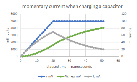
HOWEVER - taking these values R=50 ohms, C=500pF; if we assume a rise time of 20nS the maximum current would be 70mA; and only exceed 40mA for 20ns.
(I havent been able to find a figure for the rise time of an arduio output pin)
In this case I dont believe a gate resistor would be needed. However it would seem to be good practice to have a gate resistor in the region of 200 ohms.
If it's about protection of the Arduino pin then use a resistor of at least 150 Ohm (< 40 mA @ 5V). If it's about fast switching then select the right MOSFET and eventually add a bipolar driver chip.
There are discussions about this topic for years. Look for example at this topic:
In short my opinion:
The often quoted absolute maimum 40 mA is for DC current. There is no transient rating provided.
The pins are designed to drive capacitive loads - for example inputs of other CMOS circuits are also FET Gates!
Often quite heavy capacitive load is driven by Arduino pins and noone complains - piezzo speaker, a lot of inputs with long wires and so on. The interesting thing - people are worried about signal integrity at this case, not well-being of the pin.
From this I believe driving a small MOSFET without Gate resistor is perfectly safe. It is comparable to driving a few CMOS inputs. It is TBD what is "small MOSFET".
When driving a huge MOSFET its Gate capacitance may overload the pin. However from my (limited) tests and accidents the drivers (of old AVRs) are very rugged and survive a lot of abuse including short circuit to power rails, PWMing large capacitors and so on. If you use a huge MOSFET it is probably because you intend to control a heavy load. It is already stressed because the relatively weak Arduino pin will turn it on/off slowly and so it stays in the linear region for long time. Adding a Gate resistor makes this even worse. While damage of the pin driver by the transient is theoretical, damage of the power MOSFET by a slow turn on/off is very real danger. Assuming 50 Ohm Arduino driver resistance adding a "safety" 200 Ohm Gate resistor increases turn on time (and so switching losses) of the MOSFET 5 times!
The Gate resistor is not entirely useless - you may actually want to slow down turn on/off of the MOSFET. Most likely to reduce noise (i.e. on power rails). For this there is no easy way to determine the optimal value and it could be quite large. For example in one of my projects I turn on LEDs quickly but use 1M resistor to turn the MOSFET off. The LEDs slowly fade out this way and it is simpler and more smooth than PWM.
Logic level FETs making 12V PWM didn't get gate resistors and no pins died, but maybe I didn't run them long enough. 220R would be safer and I have plenty 220R's!
There is a difference between the capacitance of logic gates and power MOSFETs. Logic transistors also can have higher current limiting On resistance than Arduino outputs.
If it works for some time, under certain conditions, who can know when if will start failing?
Thanks for all your replies. .. and the link, which is very interesting.
It seems to boil down to this:
for "hobby" circuits the gate resistor is not needed - because the energy transferred in turning the FET on & off - even with normal PWM up to 31kHz - is too low to damage the arduino.
If you are using the arduino to drive a BIG MOSFET with FAST PWM (why would you?) you need to do the design properly, and probably use a driver IC.
Inductive load has no switch on loss only if it starts at zero current. This won't be true for fast PWM. In either case it is more than compensated by the switch off loss which is much higher than for resistive load.
What difference do you have in mind and why do you think it makes safer to drive the logic gate?
I have MOSFETs with an L in the name. They can switch 10A easily and gate full open by 2V. That's going to take a lot less capacity fillled.
I need to look at an AVR datasheet.... I don't recall having to include 50 Ohm Arduino driver resistance into any Arduino calculations in the past 12 years.