For this project, I am running a single, small (6mm di.) stepper motor. I require the full power available from the first driver to provide enough torque to rotate the motor’s gear. The problem is that the holding current from this driver causes the motor to overheat quickly when it is not rotating.
Is it possible to connect the same motor to a second driver to provide a much lower holding current?
This would mean I enable the the high power driver (and disable the low power driver) when the motor must rotate, and disable the high power driver (and enable the low power driver) when the motor must stay locked in position. This way, only one driver would be sending power at a time but the motor will not overheat when it is not rotating.
Please tell if you have any suggestions to solve this problem!
P.S. I have tested multiple power sources, varying both voltage and current. The only way to provide enough torque is to use the high power driver that over heats the motor when it is running a holding current to keep it locked in position.
Estrobert:
For this project, I am running a single, small (6mm di.) stepper motor. I require the full power available from the first driver to provide enough torque to rotate the motor’s gear.
By full power, I mean that driver has a power source of 9v 1amp. Where the low power driver shares the same power source, but has 100 ohm resistors on each lead to the 4 posts of the motor.
The spec of the motor doesnt matter, I am COMPLETELY over voltage and over current when rotating the motor to achieve the desired torque. But I need a way of significantly dropping the current on when the motor is not rotating ( holding current) because that is the majority of the time and it will over heat.
I cannot use a digital potentiometer because I don’t enough spots on my Arduino to connect it.
If you need only 2 current settings then a digital output can be used to set the control voltage on the EasyDriver with a resistor.
This voltage is available on the "test point" TP1. If you add a resistor between that point and an Arduino output pin, you can drive that point higher or lower than the setting on the bare board.
Note that you cannot turn the adjustment pot on the EasyDriver all the way to max. That just connects it directly to 5V on the EasyDriver board and you can't move it from there. But any other setting will respond to this adjustment.
Maybe start with a 10K resistor to the Arduino pin. Higher values like 22K will give a smaller gap between high and low current. Lower values like 3.3K will give a bigger swing between high and low current.
Ahh ok i will give that a try. but the 10k pot on my easy drivers has been turned past the limit and no long works (it only provides the max current now).
Is the same solution possible with these drivers?:
I have a bunch left over from a project that I ended up never using.
Am using an A4988 driver with a 9V 1amp power source to run a small 6mm dia stepper motor
I am running into a problem because I need to over current the motor when it is rotating to achieve the desired torque, but I need to drastically decrease the holding current when the motor is not rotating to avoid over heating.
Is there a way to achieve this two current setting with out a digital potentiometer (I don't have enough pins to run one on my arduino)?
Ok. It is easier with that driver board because Vref is brought out to a regular pin. From the Pololu instructions the current limit is given as 2.5 times the voltage at Vref.
Are you able to calculate a voltage divider that will give the two current settings you require from a 0-5V Arduino pin?
Please tell me how many amps you want for "full". Note that it is not a good idea to go to the absolute maximum rating of the A4988 as that board doesn't have enough cooling.
So for 500mA, you need 0.2V on that reference pin. For an eighth of this (62.5mA) the voltage should be 0.025V
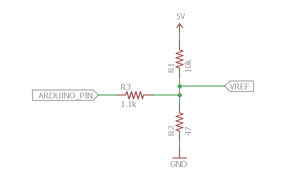
If you can desolder the adjustment potentiometer, this will be a lot easier. We can drive the pin directly. Use the circuit below.
If you can't desolder the pot then try the circuit without R1 and adjust the pot until you get voltages close to what you want. I suggest that an eighth is probably too low. You may want your holding current higher. In that case, change R3 to 3.3k and R2 to 100 Ohms. Increasing R3 will reduce the difference between high and low current modes. Increasing R2 will give overall more current. Experiment with it!