Hi everyone, I think I might have misunderstood how UART comms works. I am quite new to the topic, but here is my question:
Task to solve
I want to read data from the TF02-PRO LiDAR (TF02-PRO link to download docs) with a TTGO LoRa32 SX1276 OLED board (TTGO board documentation).
Data to take into account:
- TF02-PRO has 4 wires: Red(Vcc), Black(GND), Green(TX), White(RX)
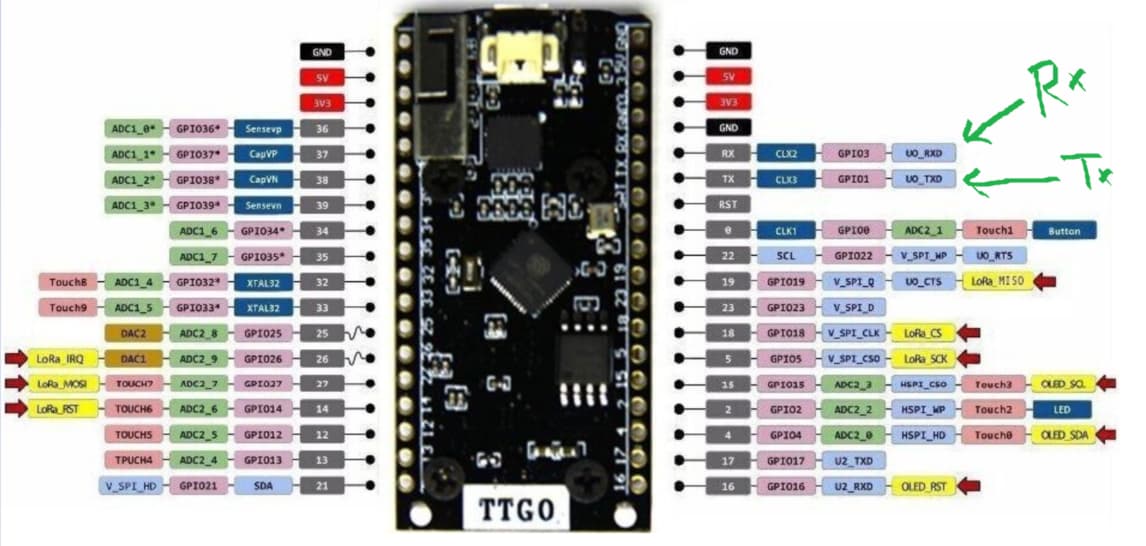
- Pins used from TTGO board to use RX, TX are GPIO03 (RX) and GPIO01 (TX)
Solution attempted
The connection is the one displayed in the following image:

As I tried to show, the TTGO board is directly connected to the computer so as to be supplied with voltage. On the other side, As I saw in the docs of the TF02-PRO, it can be supplied with 5V~12V, so I've opted for a 12V power supply. Finally, the Rx output of the TF02-PRO LiDAR is connected to the TX GPIO from the TTGO board, and the Tx output of the TF02-PRO is connected to the RX GPIO from the TTGO board.
In order to achieve the communication, the program I run is the following:
#include <HardwareSerial.h>
#include <Wire.h>
#include <Adafruit_GFX.h>
#include <Adafruit_SSD1306.h>


// SSD1306Wire  display(0x3c, 500000, SDA, SCL, GEOMETRY_128_64, GPIO10); // addr , freq , SDA, SCL, resolution , rst

HardwareSerial ss(0);

#define RXD0 3
#define TXD0 1

#define OLED_SDA 4
#define OLED_SCL 15
#define OLED_RST 16
//Display characteristics
#define SCREEN_WIDTH 128 ///< OLED display width, in pixels
#define SCREEN_HEIGHT 64 ///< OLED display height, in pixels


Adafruit_SSD1306 display(SCREEN_WIDTH, SCREEN_HEIGHT, &Wire, OLED_RST);///< Create an Adafruit_SSD1306 object called display

String inputString = "";
char inChar;

const int HEADER = 0x59;

void displayOLEDMsg(String msg){
  display.clearDisplay();
  display.setTextColor(WHITE);
  display.setTextSize(2.0);
  display.setCursor(0,50);
  display.print(msg);
  display.display();

}


void setup(){
  // Serial.begin(9600);
  ss.begin(115200, SERIAL_8N1, RXD0, TXD0);

  pinMode(OLED_RST, OUTPUT);
  digitalWrite(OLED_RST, LOW);
  delay(10);
  digitalWrite(OLED_RST, HIGH);

  //Initialize OLED
  Wire.begin(OLED_SDA, OLED_SCL);
  if(!display.begin(SSD1306_SWITCHCAPVCC, 0x3c, false, false)) { // Address 0x3C for 128x32
    // Serial.println(F("SSD1306 allocation failed"));
    for(;;); // Don't proceed, loop forever
  }

  displayOLEDMsg("LoRa OK!");

}


void loop(){
  if(ss.available()){
    displayOLEDMsg("Data read...");
    // Serial.print("Recibiendo...");
    if(ss.read() == HEADER){
      displayOLEDMsg("LiDAR data");
    }
    else{
      displayOLEDMsg("");
    }
  }
}
which does the following:
After setting up the pins that will be used as Rx and Tx, and configuring the OLED display, it begins the HardwareSerial SerialPort, specifying the baudrate, the output format and the Rx and Tx pins. In the main loop, it checks if ther is data available in the serial port, if there is any, it displays that there is data available. Then, it checks whether the data matches the TF02-PRO Header (specified in the docs 0x59) or not. If it matches, it displays that the data comes from the LiDAR.
Expected behaviour
Running the program should result in the TTGO board display showing the message LiDAR data, as the data captured from the LiDAR should be sent to the board via UART
Actual behaviour
It never passes the serial port availability condition, which indicates that no data is being sent from the LiDAR to the board
My Issue
I don't know if I have misunderstood how UART works, and if there is any extra configuration that I'm missing or something. If so, please let me know what else should I do. If any extra info is needed in order to give me an answer, please let me know
Many thanks in advance!