I would like to implement the TF02-Pro with the ESP32. I know that it works with Arduino so I've assumed that it will work with ESP as well.
The TF02-Pro has 4 wires defined as: red +5V, black GND, green TX, white RX.
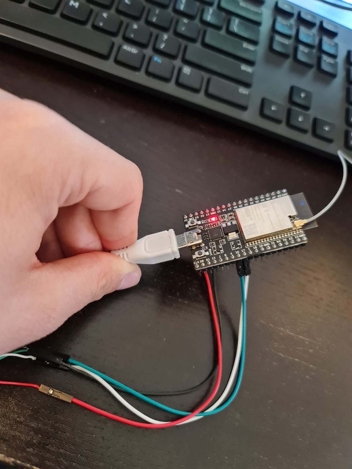
I have connected them as follows:
Sensor 5V to ESP 5V;
Sensor GND to ESP GND;
Sensor TX to ESP RX;
Sensor RX to ESP TX;
Also, the TF02-PRO adopts the serial port data communication protocol.
Communication interface: UART
Communication level: LVTTL(3.3V)
Default baud rate: 115200
Data bit: 8
Stop bit: 1
Parity check: None
I have followed this guide: https://www.roscomponents.com/en/index.php?controller=attachment&id_attachment=309
This is the code resulting:
#include <Arduino.h>

#define RXD2 16
#define TXD2 17

int dist;     // LiDAR actually measured distance value
int strength; // LiDAR signal strength
int check;    // check numerical value storage
int i;
int uart[9];             // store data measured by LiDAR
const int HEADER = 0x59; // data package frame header

void setup()
{
  // put your setup code here, to run once:
  Serial.begin(115200);
  Serial.println("Started.");
  Serial2.begin(115200, SERIAL_8N1, RXD2, TXD2);
}

void loop()
{
  if (Serial2.available()) //check whether the serial port has data input
  {
    if (Serial2.read() == HEADER) // determine data package frame header 0x59
    {
      uart[0] = HEADER;
      if (Serial2.read() == HEADER) //determine data package frame header 0x59
      {
        uart[1] = HEADER;
        for (i = 2; i < 9; i++) // store data to array
        {
          uart[i] = Serial2.read();
        }
        check = uart[0] + uart[1] + uart[2] + uart[3] + uart[4] + uart[5] + uart[6] + uart[7];
        if (uart[8] == (check & 0xff)) // check the received data as per protocols
        {
          dist = uart[2] + uart[3] * 256;     // calculate distance value
          strength = uart[4] + uart[5] * 256; // calculate signal strength value
          Serial.print("dist = ");
          Serial.print(dist); // output LiDAR tests distance value
          Serial.print('\t');
          Serial.print("strength = ");
          Serial.print(strength); // output signal strength value
          Serial.print('\n');
        }
      }
    }
  }
}
The issue is that I have no output except Serial.println("Started.");.
I have also tried changing the pins:
#define RXD2 22
#define TXD2 23

void setup()
{
  Serial.begin(115200);
  Serial.println("Started.");
  Serial2.begin(115200, SERIAL_8N1, RXD2, TXD2);
}
And I still have no output. (other than Serial.println("Started.");.)
I have opened the sensor's case and I have measured the voltage input and it's around 4.6V. The Product Manual of TF02-Pro says that the supply voltage should be 5V~12V.
I have also tried the code from here: TF02 Lidar For Arduino And Pixhawk | How To Use but I still got no output.
If this works on an Arduino, shouldn't it work on an ESP32 ?
Thank you.


