Hello to everybody,
I am a bit confused about how to read the output of an ultrasonic sensor with UART controlled.
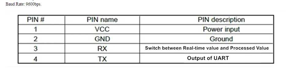
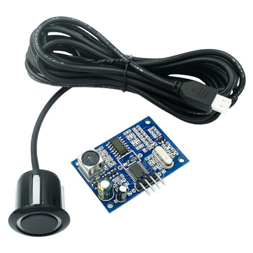
The sensor is this AliX ultrasonic sensor
Does anyone can help me with a code example?
I tried this First test code that is explicitly for UART controlled and I also tried some code in the comments in the product page but I did not get a proper output value: no value in the First test code.
Did anyone already use an UART controlled sensor? I have to better understand the difference between UART controlled and UART automatic.
may be the protocol is not the same as the one from DFRobot
try to see if anything get printed automagically (may be what they mean by "UART automatic". In the "UART controlled" you have to send a command to get a reading)
#include <SoftwareSerial.h>
SoftwareSerial mySerial(7, 8);
void setup() {
  Serial.begin(115200);
  mySerial.begin(9600); // try various baud rates
}

void loop() {
  if (mySerial.available()) {
    int r = mySerial.read();
    if (isalnum(r)) {
      Serial.println((char) r);
    } else {
      Serial.print("0x");
      Serial.println((byte) r, HEX);
    }
  }
}
as we don't know which baud rate is used, you might have to try different common baud rates in this line
Thank you for your answer. I tried following baud rates with NO output: 9600, 19200, 38400, 57600, 115200.
I also tried to add Serial.println("check"); at the beginning of the loop to be sure that the board was up and running with an USB adapter. "check" was printed correctly.
In the comment of the page product, one user that bought the product said that he got the correct output using following (part) of the code:
  //Define input and outputs
  pinMode(pinTrig, OUTPUT);
  pinMode(pinEcho, INPUT);
  digitalWrite(pinTrig, HIGH);

uint16_t getSonarDistance(int Trig, int Echo) {
  // 15 ms @ 340 m/s = 5m round trip
  const unsigned long MEASURE_TIMEOUT = 15000UL;

  // Trigger the sensor
  digitalWrite(Trig, LOW);
  delay(5);

  // Read the signal from the sensor
  long duration = pulseIn(Echo, HIGH, MEASURE_TIMEOUT);

  // Set it back to HIGH until next Trig
  digitalWrite(Trig, HIGH);

  //convert into a distance
  distance = int(duration / 57.5);

  return distance;
}
I think that UART controlled means that there is the need of the trigger to read the output.
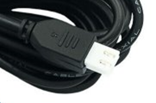
In the datasheet posted above i can read:
When the cable “RX” receives a trigger pulse with falling edge or any serial port
data, the module makes a measurement, the cable “TX” will output a
measurement distance value when the measurement is finished every time
Is it enough to trig the output enabling/disabling a digital I/O?
It’s possible that these are 4 different products, in which case I wouldn’t know which one I’m buying, I just have to hope there’s some description within the package to work with.
If it’s one product with several output options, the data in the description on the AliX site is severely lacking on how to set 4 options with 1 input, again just hoping the accompanying paper tells more.
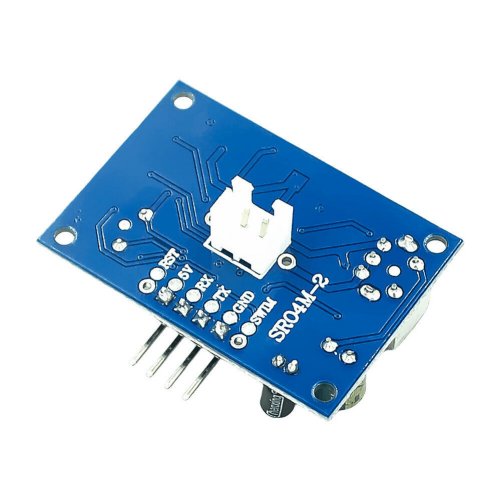
Looking at those pictures, I’m not sure these belong together. The sensor has a USB plug, the board has a 2 pin HY connector. Am I oldfashioned with my idea that a vendor should show what it’s really selling?
Or: do they really sell something from one box with something from another box without questioning if they go together?