I am using an ULN2003A to turn two lasers on and off on command. I can see the input voltage going up when I ask it to but the output voltage remains at zero. The chip is getting a good five volts of power input. Have tried two different chips with same result. Am puzzled!
You really need to give us more information.
We need to see a schematic and a good picture of your wiring.
.
The lasers should be connected between supply and an output pin of the ULN2003.
The chip is just seven switches to ground.
Post a diagram and/or picture of your setup.
Leo..
You are probably connecting the load (lasers) the wrong way, between the ULN2003A and ground. Thats why is not working.
When you drive the input of ULN2003A high, the output goes low - it's a low-side switch, not high side switch. If you must have a high side switch (which you usually don't; high side switches are worse - either worse specs or higher price, all else being equal), use something like a UDN2981 (or discrete transistors).
Sorry, should have been more complete. I am trying to build a CiClop, or PyClop (have not decided) 3D scanner. Attached is the fritzing diagram of the part of the circuit that controls the lasers.
The breadboard is a bit hard to get a good picture of.
Thanks,
Will
It looks like I got my answer as I was posting the diagram! It seems that I completely miss-understood how the ULN2003A works :-o
I feel like I am either missing something simple or being incredibly dense...or both! I have pared things down to the minimum configuration applying what I think I was told to do above and it still does not do what I want it to do!
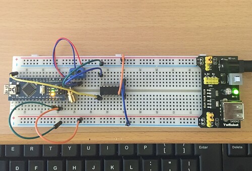
Here is the wiring diagram and a picture of the actual breadboard:
Here is the sketch:
void setup() {
  pinMode(12, OUTPUT);
  pinMode(13, OUTPUT);
}

void loop() {
  digitalWrite(13, HIGH);   // turn the LED on (HIGH is the voltage level)
  digitalWrite(12, HIGH);   // turn the Laser on (HIGH is the voltage level)
  delay(10000);              // wait for a 10 seconds
  digitalWrite(13, LOW);    // turn the LED off by making the voltage LOW
  digitalWrite(12, LOW);    // turn the Laser off by making the voltage LOW
  delay(10000);              // wait for a 10 seconds
}
I can see the voltage oscillating on pin 12 but it never changes on the output side of the ULN2003A.
Thanks,
'Def not Wiser
Wisar:
I can see the voltage oscillating on pin 12 but it never changes on the output side of the ULN2003A.
Nor will it. In this situation, you are doing wrong, exactly what we thought - you are connecting the laser to ground instead of to the +5 V supply.
Is this by the way, the laser you intend to actually use? If it is, and it has mounted on the back of it a resistor marked "910", then it should be safe to connect it directly between pin 12 of the Nano and ground.
I mention pin 12 rather than pin 13 as pin 13 already has a LED connected and drawing power. The laser specified with the "910" resistor on the back will draw 25 mA or less and the Arduino can actually handle three or four of them directly connected to different pins - but no more than four.
Please post a proper schematic. It would be much easier to get help.
Watcher:
Please post a proper schematic. It would be much easier to get help.
He posted an actual photo.
Ok.......first, thanks for everyones help on this. I really thought that I was being dense but in reality I was also careless.
I had actually tried hooking the laser up every which way from Sunday. I did miss interpret what I was told above, as you can see from the diagram and picture, but I had also tried it the right way and that had not worked either!
Why you ask?
BECAUSE THE ULN2003 WAS NOT PROPERLY SEATED IN THE BREADBOARD!!!!!!!!!!!
Again, thanks for the help. This has to be one of the best forums out there for getting good help quickly.
Cheers,
Will
The Nano also seems to be (under)powered through Vin ![]()
Leo..


