I'm making a oscillator for the piezo disk pictured below. It runs at 1.677MHz. So far I'm trying to use an H-bridge configuration as it was proven a reliable circuit for experimenting in an article.
Here's what I came up with. Once circuit shows the Arduino outputting 2 1.677MHz signals, with a 180* shift between them. The other uses a PNP transistor to switch on transistor Q2 & Q4
My questions are:
Can the Arduino UNO output something at that high of a frequency (I read on a couple forums that the max is only 1MHz)
Would it be worth it to get PNP power transistors for Q2 and Q4?
The circuit you show wouldn't actually work even with low frequencies. For the two upper N-channel MOSFETs to work, assuming they're a logic-level type, the gate needs to be driven by at least 26V, 2V higher than the supply voltage. 5V applied to their gates won't do anything.
An Arduino can switch at that sort of frequency. Not so sure about a precise 1.677MHz, though you could get something in the neighbourhood of that. Check out the "PWM Frequency Library". A search will soon find it. It can produce outputs up to 2MHz.
Your best bet is possibly NPN and PNP complementary transistors. Quite a few transistors can switch at 2MHz+, but gain drops off as the frequency increases. This will often be listed as the gain-bandwidth product in datasheets. GBW/f = gain
More info on GBW:- Gain-Bandwidth Product
Chill_Polins:
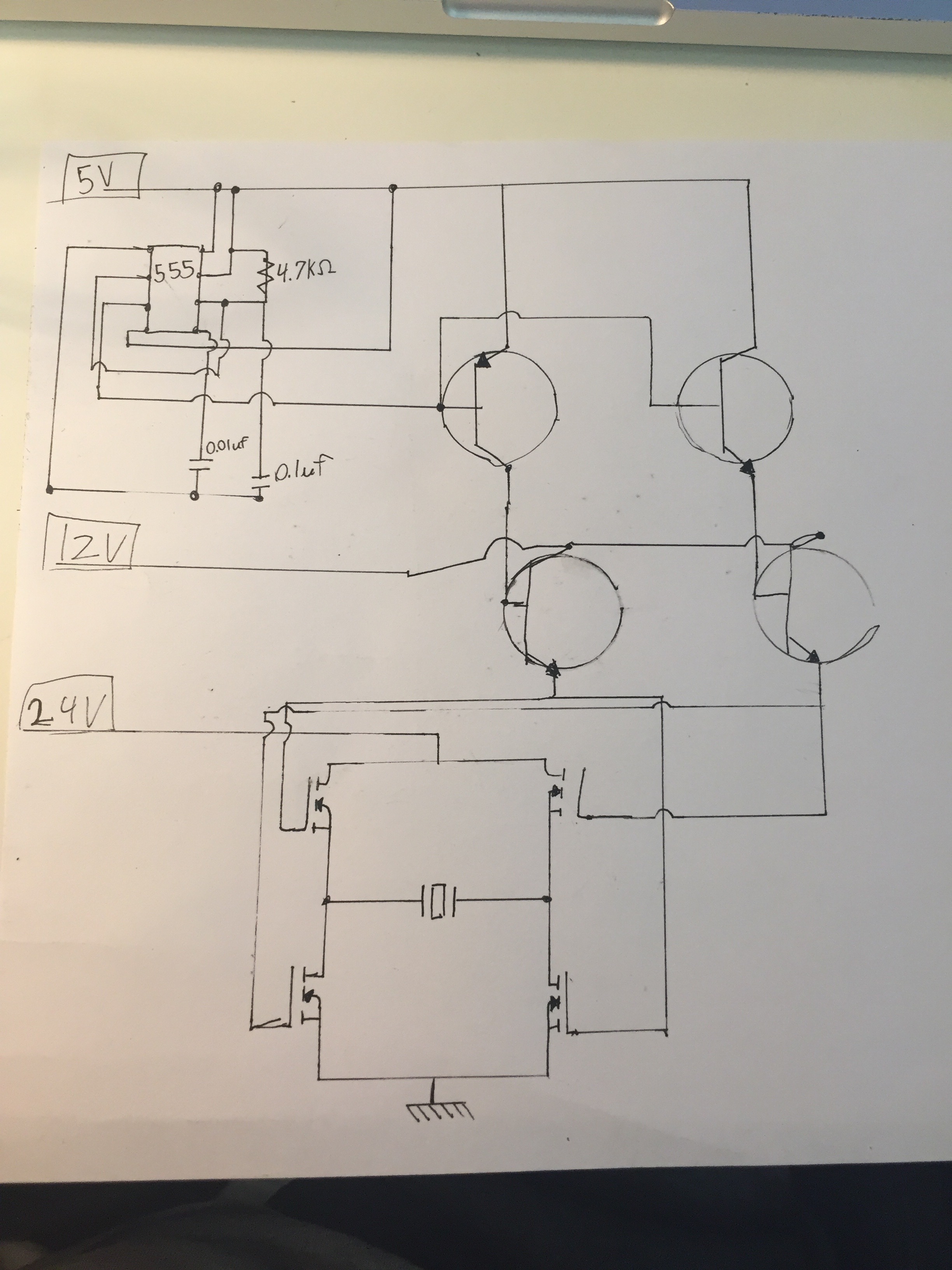
This is my circuit. Any idea what I'm doing wrong?
That's a very unconventional way to draw the schematic.
Without studying your circuit further, you still ignored what I said the other day - the two upper N-channel MOSFETs cannot work in that configuration. I said, "the gate needs to be driven by at least 26V, 2V higher than the supply voltage. 5V applied to their gates won't do anything."
12V applied to their gates won't do anything either.
And in your circuit, even if the MOSFETs would work, you'd have a dead short across the 24V rails because upper and lower MOSFETs would be 'on' at the same time. (Just as well the upper MOSFETs can't switch on. )
You need to re-think your whole circuit, and either go to a transistor H-bridge or N-channel MOSFETs with a high-side driver. You'd have a better chance with P-channel MOSFETs on the high side, but like in this circuit, you need to ensure that two MOSFETs on each side can never be 'on' at the same time.
Back to the drawing board, I'm afraid. Try a Google search for driver circuits in stead of trying to 'cook' your own without the necessary knowledge.
Sorry to sound so blunt, but I did tell you the other day and you chose to ignore me.
Edit: The phrase "MOSFET H-bridge" should yield plenty of results, especially if you do a Google image search.
(Actually, I just had a quick peek and there are a lot of dud circuits there too. Be discriminating in which you choose to copy. You want one with P-channel upper MOSFETs and N-channel lower MOSFETs, and a driver that doesn't allow both MOSFETs on either side to be 'on' at the same time.
Wawa:
What is the 555 doing in that circuit.
That's a slow/old 100khz device.
Some might be pushed to 500khz.
1.677Mhz is a no.
Leo..
Quite right. I'd overlooked that aspect of the design. Yet another reason for a complete re-think. A CMOS 555 should be able to do it though. Possibly a TLC555.
Edit: And I just had a look - a TLC555 can go up to about 2MHz, so it would just do it. But not with the values shown in the schematic. And not with that circuit layout either, now that I've looked more closely at it.
Hi,
The LM555 circuit is a bit suspect too.
For astable mode there should be 2 resistors in the timing circuit and pin 7 should not be connected to 5V.
Also it will not be 50% duty cycle.
OldSteve:
That's a very unconventional way to draw the schematic.
Without studying your circuit further, you still ignored what I said the other day - the two upper N-channel MOSFETs cannot work in that configuration. I said, "the gate needs to be driven by at least 26V, 2V higher than the supply voltage. 5V applied to their gates won't do anything."
12V applied to their gates won't do anything either.
And in your circuit, even if the MOSFETs would work, you'd have a dead short across the 24V rails because upper and lower MOSFETs would be 'on' at the same time. (Just as well the upper MOSFETs can't switch on. )
You need to re-think your whole circuit, and either go to a transistor H-bridge or N-channel MOSFETs with a high-side driver. You'd have a better chance with P-channel MOSFETs on the high side, but like in this circuit, you need to ensure that two MOSFETs on each side can never be 'on' at the same time.
Back to the drawing board, I'm afraid. Try a Google search for driver circuits in stead of trying to 'cook' your own without the necessary knowledge.
Sorry to sound so blunt, but I did tell you the other day and you chose to ignore me.
Edit: The phrase "MOSFET H-bridge" should yield plenty of results, especially if you do a Google image search.
(Actually, I just had a quick peek and there are a lot of dud circuits there too. Be discriminating in which you choose to copy. You want one with P-channel upper MOSFETs and N-channel lower MOSFETs, and a driver that doesn't allow both MOSFETs on either side to be 'on' at the same time.
Apologies my computer didn't load your last comment
The MOSFETS I own (IRF510s) have gate voltages of 10V..I actually did end up triggering them, only the circuit would only work on lower frequencies...If I went too high the pulses slowed down. (I tested with an 8 Ohm speaker.)
When you say 'upper' do you mean the left and right diagonal? because if you have identical mosfets on the same side (example top right-bottom right) then wouldnt the current just flow between them and not hit my disk in the center.
I will continue looking at bridges, I think the the key for me will be finding transistors and MOSFETS (JFETS) that keep wave resolution at higher frequencies.
Be blunt...I'm a 100% noob and I don't like wasting my time or yours.
But you say the Gate must be driven by a higher voltage?
Chill_Polins:
Apologies my computer didn't load your last comment
The MOSFETS I own (IRF510s) have gate voltages of 10V..I actually did end up triggering them, only the circuit would only work on lower frequencies...If I went too high the pulses slowed down. (I tested with an 8 Ohm speaker.)
When you say 'upper' do you mean the left and right diagonal?
No, I mean the two top ones, hence 'upper'. (One on each side.) They cannot switch on in your circuit.
I will continue looking at bridges, I think the the key for me will be finding transistors and MOSFETS (JFETS) that keep wave resolution at higher frequencies.
MOSFETs and JFETs are two different animals, although related. Junction Field Effect Transistors and Metal Oxide Semiconductor Field Effect Transistors
But you say the Gate must be driven by a higher voltage?
Yes, twice now. (This is the third. ) If you have N-channel MOSFETs connected to the positive rail, their gates MUST be taken higher than the positive rail to switch on. About 10V higher for a standard MOSFET, and at least 2V higher for a logic-level MOSFET.
If you look carefully through the Google search results on MOSFET H-bridges, you'll see that many of the complete circuits use "P-channel" MOSFETs on the high side. (The little arrow points out, not in.) To use N-channel, you need drivers capable of generating a voltage higher than the supply rail.
I honestly believe that you should take some time out to learn a little more about electronics. You need to have at least a basic understanding of electronics and how the components work before you get into circuit design. There's a very good reason that some of us went to school for a few years to learn (just the basics of) this stuff.
TomGeorge:
Hi,
The LM555 circuit is a bit suspect too.
For astable mode there should be 2 resistors in the timing circuit and pin 7 should not be connected to 5V.
Also it will not be 50% duty cycle.
Tom....
Yep, that's what I meant by "And not with that circuit layout either, now that I've looked more closely at it."