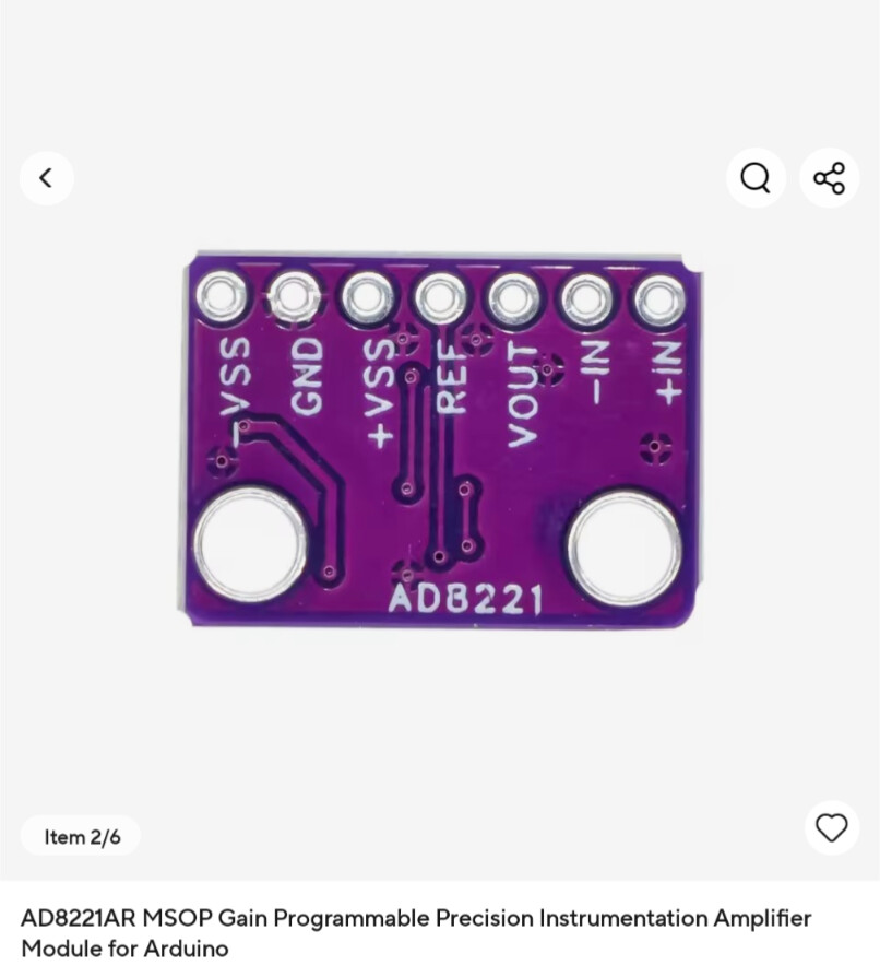
I am hoping to use the instrumentation amplifier (show in the image) but I am unable to find a datasheet. I am wondering if anyone has experience, or a good guess as to how this chip will work?
Typically, an instrument amp will have 2 reference pins to control the amplifier gain, but this doesn't seem to have that?
That amplifier is by Analog Devices. They will have a lot of information on that device and more likely than not, articles on applications and instrumentation amplifiers in general.
This is one of my pet peeves with these arduino modules. It would cost pennies to add a voltage inverter so you could run it from +5v only and they could sell it for a few bucks more.
The just never think about how these things will be used and it's just a race to see who can be cheapest.
Thanks for the replies. I intend to use this module to amplify a pressure sensor which provides a sensitivity of 0.2mV / kPa.
For the operating range I require, this will output a range of 0 mV to 40mV. If the board has a fixed value of 499Ω (G = 100), I think that will be fine for my applications. It will lose a little accuracy as the Uno reads up to 5V (with ADC) but, good enough for my applications.
Thank you for your help.
What is the best way to mirror the voltage and provide a negative supply? My current DC power source does not provide any negative voltage lines.
That would be a complete waste of your time. 40 mV/ (5 mV/ADC step) = 8 ADC steps for the range. On the other hand, it would be a good learning experience.
Tha AD8221 can swing between 0volt and 3.8volt on a bi-polar supply,
which could give you about 778 data points (in theory) with a 10-bit A/D.
Must protect the Arduino pin against negative voltages though with a resistor/diode clamp.
Leo..