Hi, Looking for some advise on amping the signal from a medical pressure transducer. Ive seen some people suggest a HX711 Arduino module, which I've also seen used for load cells. Just not entirely sure if it’ll be applicable for my device.
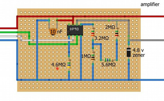
I’ve been using a custom circuit from another paper I found online using the OP90 from Analog Devices (red : 5v, blue:GND, grey: A1 pin(analog)) but got weird result, so exploring other options if anyone has done something similar.
That could be a good choice. The transducer is in effect a load cell (Wheatstone bridge sensor).
Whether the differential voltage range of the output for the pressures to be encountered matches the input range of the HX711 is something you need to think through.
The input offset voltage is defined as the differential DC voltage required between the inputs of an amplifier, especially an operational amplifier, to make the output zero.
The relevant specification is the input voltage range, which is 0 to 3.5V (with Vcc = 5V).
That said, the OP90 is an old design, not "rail to rail" and for that reason is a poor choice.
I didn't look into it that deeply. According to the wiring diagram, I see a single-polarity power supply of +5 volts, up to 1.5 millivolts at the input. At a gain of 700, we go beyond the linear gain range. And yes, radio is just a hobby for me, but in general I herd sheep in my high-mountain village.
It has a different sensor that outputs microvolts, the gain is OP90, it accepts 1000 , and then all the calculations are correct. You have a different sensor, and using HX711 would be more correct.
If there is a sensor in your range that immediately produces a digital signal, this would be the ideal solution.
The sensor you have is a resistive bridge sensor with a differential voltage output, just like a load cell.
Your options are 1) use a differential amplifier (not a single-ended amplifier like the posted OP90 circuit) followed by an ADC of your choice.
Or 2) use the HX711, which is a differential amplifier followed by an ADC in one convenient package.
For the latter choice, study the data sheets for the sensor and the HX711 and decide if the common mode voltage and differential output swing of the sensor matches the common mode voltage and differential input range of the HX711.
The key specification of the sensor is the sensitivity, which is 5 uV/V/mm Hg.
This means (for example) if 5V is applied to the sensor with 0 mm Hg pressure input, common mode voltage output will be 2.5V and the differential voltage output will be zero.
If 1 mm Hg pressure is applied, the differential voltage output will be 5uV*5 = 25 uV.
Yep the HX711 seems like the more convenient option. I was initially using a Honeywell ABP series sensor, which has analog output that was perfect for Arduino, but ran into physical limitations with fluid setup.
Another problem with an opamp is feeding it into the 10-bit A/D of an Uno.
That won't give you a high resolution (pressure steps).
The HX711 comes with a 24-bit A/D and an excitation voltage stabiliser.
Leo..
Even taking into account that we will use only 20% of the capabilities of the ADC, the result will be significantly better than if we use the ADC Arduino Nano (5x5x350x128)
An invasive blood pressure transducer for critical care. Are you doing this out of interest?
Just curious as a long term user of blood pressure monitors both in and out of clinics. Pacemaker user to boot, so medical instrumentation is of personal interest too.