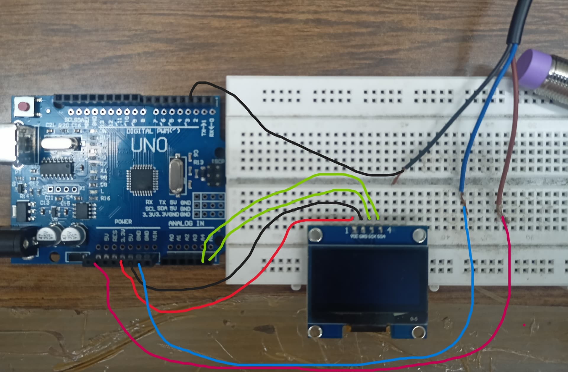
I am trying to measure the rpm of a motor using arduino uno clone and a proximity sensor. I have also used an oled display to show the number of rotations and the rpm itself. Everything is working fine, but the proximity sensor picks up multiple signals at a time (varying from 1-7 per revolution) and increments the same value. This leads to multiple rotation read for a single rotation and fluctuation in rpm. I am using NPN NO 3 wire inductive proximity sensor, 1.3" OLED display and a 200 rpm geared motor with 10 amps PWM controller. The sensing part is an allen key connected to the motor through a drill chuck. The connections are as follows:
OLED:-
Vcc - 5v
GND - GND
SCK - A5
SDA - A4
Inductive Proximity Sensor:-
Brown - 5v
Blue - GND
Black - PIN 2
I have provided the code also.
// Pin connected to the sensor output
#include "U8glib.h"
U8GLIB_SH1106_128X64 oled(U8G_I2C_OPT_NONE);
const int sensorPin = 2;

// Variables
volatile int rotationCount = 0;
volatile bool rotationDetected = false;
unsigned long prevTime = 0;
float rpm = 0.0;

void setup() {
  // Initialize serial communication
  Serial.begin(9600);

  // Attach an interrupt to the sensor pin
  attachInterrupt(digitalPinToInterrupt(sensorPin), countRotation, FALLING);
}

void loop() {
   oled.firstPage();
  do {
    page1();
  } while (oled.nextPage() );
  if (rotationDetected) {
    unsigned long currTime = micros();
    unsigned long timeDiff = currTime - prevTime;

    // Calculate RPM
    rpm = 60000000.0 / timeDiff; // Convert to RPM
    rotationDetected = false;
    prevTime = currTime;
  }
}

void countRotation() {
  // Increment the rotation count
  rotationCount++;
  rotationDetected = true;
}
void page1(void) {
  oled.setFont(u8g_font_profont12);
  oled.setPrintPos(0, 10);
  oled.print("No of rotation : " );

  oled.setPrintPos(0, 25);
  oled.print(rotationCount);
  oled.setPrintPos(0, 40);
  oled.print("RPM of DC Motor :");
  oled.print(rpm);
}
Would like to hear from the community to solve the issue.
Yes, I kept the sensor away and check by using another metal plate by simply bringing it closer and extending. The problem still prevails (multiple counts increase occasionally when I bring close just once). I didn't use any pullup resistor but the setup works fine. I have attached an edited image of the setup in another reply, please find it.
void setup() {
  // Initialize serial communication
  Serial.begin(9600);
  pinMode(sensorPin,INPUT_PULLUP);
  // Attach an interrupt to the sensor pin
  attachInterrupt(digitalPinToInterrupt(sensorPin), countRotation, FALLING);
}
You should know that NPN outputs require a pullup resistor to Vcc of the controller. Start with 1k and reduce it if the phantom counts did not disappear.
Sorry, because of my poor English, can only use translation software, reply to mean, in front of the arduino itself is take pull resistance, you only need to write :“pinMode (2, INPUT_PULLUP); ” Is ok!
I tried this but the count deviation just increased (deviated for each detection). Without this the deviation was encountered once every 3-5 detection.
Unless you ground the metal plate to the Arduino ground, you are waving a BIG antenna around sensitive circuitry. Try grounding the plate to the Arduino ground and then wave it around the sensor.
Can you tell us the part number of the sensor?
Can you please post a link to data/specs of the sensor?
Can you please post images of your project, showing the sensor, the motor and the shaft, and the target on the shaft that the sensor detects on each revolution.
Please show us how you have the sensor positioned to measure RPM.
What size is the target?
How fast are you rotating the motor?
All these things are important so we know how your project is constructed.
The fact the your original code had no pinMode statement for the sensor input, yet you were getting "readings" worries me.
Do you have a DMM? Digital MultiMeter?
Thanks.. Tom..
PS. I'm off to bed, 33 minutes past midnight here, and I undisputedly need my beauty sleep.
Why can't you post a photo of the actual connections? They must exist, for you to report the problems. I would prefer to solve a real problem, not a hypothetical one that may not even exist.
This only tells me how you believe you connected it. As a diagram, it doesn't come close to a schematic, it only barely suffices as a wiring diagram. If you give the bare minimum here, that is what you get back.
The target is an allen key face (hexagon of side size 2mm).
The motor was tested between 50 rpm to 200 rpm. Yes, I have a digital multimeter.
The proximity sensor's working range is 6-36V as mentioned in the catalogue but it works just fine with +5V of arduino board. I have also tried the sample with 12V supply also but the problem still prevails. So i decided to go with the 5V itself for simplicity of connection.
The exact pin configuration images and demonstration video is provided in post #19. Please refer it.
Hi,
So you are hand holding the sensor and the motor as the shaft rotates.
Can I suggest you put restrain the motor so it will not move.
Make a bracket to hold the sensor stable so it can read a stable input and produce a stable input pulse to the UNO.
Your sensorspecs.
Features/Specs:
Model: JG-GI12-04N1
Manufacturer: Jigo
Material: Metal and plastic
Operating Voltage: 6 ~ 36 VDC
Output Type: NPN Normally Open
Detection object: Metal Objects
Detection distance: 4 mm
Output Current: 300 mA
Total Length of Sensor: 55mm
Thread length: 35mm.
Outer (Theard) Diameter: M12
Polarity protection: yes
Surge protection: yes
Short circuit protection: yes
High repeated positioning accuracy
High switching frequency
Wide voltage range
Antivibration, dust, water, and oil prevention
Reverse power protection, short circuit protection, directly connecting with PLC
Can replace small switches and limit switches
Working temperature(°C): -25 ~ +70, ±15%
Cable Length: Approx 1.5 Meter
Dimensions: 12 mm Screw Diameter
Note the detection distance == 4mm, you need to mount your hardware on a STABLE frame.
Lets do some maths.
69 RPM = 69 / 60 RPS = 60 / 69 = 0.869 seconds period of rotation.
72 RPM = 72 / 60 RPS = 60 / 72 = 0.833 seconds period of rotation.
The difference is 36ms, you need a physically STABLE test bench.
Note the output current can be up to 300mA, I would suggest you use an external pullup resistor to have at least 50mA.
These are industrial devices.