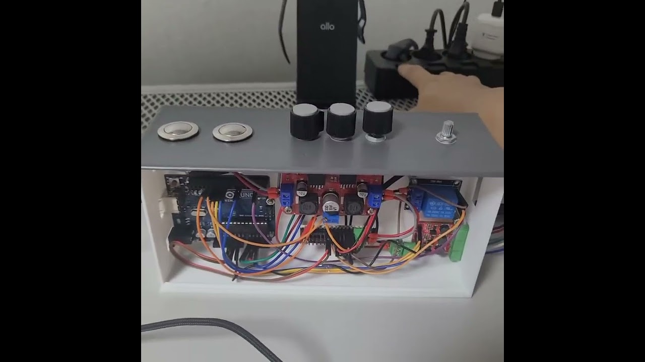
Hi all! I made a 10W LED Color and Brightness controller for my own use. despite it works well, there's a problem.
I use 12V SMPS to power LED module, and when I turn on SMPS, at that instant, LED turns on and off very quickly.
despite I added a relay module to solve this problem, but it seems like that both NO - COM and NC - COM are short when module is not powered with 5V VCC.
(1) Why this happens?
(2) How Can I prevent LED turning on right after supplying 12V input, and before arduino is on?
[video]
[schematics of project]
[arduino code]
#include <FastLED.h>

#define LED_R 9
#define LED_G 10
#define LED_B 11

#define STRIP_DIN 6
#define STRIP_LED_NUM 21

#define POT_R A1
#define POT_G A0
#define POT_B A2

#define PUSH_1 12
#define PUSH_2 13
#define RELAY 2

CRGB led[STRIP_LED_NUM];
bool push1_pressed_now = false;
bool push1_pressed_before = false;
bool push2_pressed_now = false;
bool push2_pressed_before = false;

bool led_on = false;
bool strip_on = true;

// Timing variables
unsigned long previousMillis = 0;  // Stores the last time LEDs were updated
const long interval = 100;         // Interval at which to update LEDs (in milliseconds)

// Stores previous potentiometer values to detect changes
int prev_pot_R_val = 0;
int prev_pot_G_val = 0;
int prev_pot_B_val = 0;

bool is_button_pressed(int button_no, bool &check_now, bool &check_before);

void setup() {
  Serial.begin(9600);
  // Initialize pins
  pinMode(LED_R, OUTPUT);
  pinMode(LED_G, OUTPUT);
  pinMode(LED_B, OUTPUT);

  pinMode(POT_R, INPUT);
  pinMode(POT_G, INPUT);
  pinMode(POT_B, INPUT);

  pinMode(PUSH_1, INPUT_PULLUP);
  pinMode(PUSH_2, INPUT_PULLUP);

  FastLED.addLeds<WS2812B, STRIP_DIN>(led, STRIP_LED_NUM);
  for (int i = 0; i < STRIP_LED_NUM; i++) {
    led[i] = CRGB::White;
    FastLED.show();
    delay(50);
  }

  pinMode(RELAY, OUTPUT);

  // Adjust PWM frequency to 100 Hz
  // For Timer1 (pins 9, 10), set prescaler to 1024
  // This changes the PWM frequency from 490 Hz to approximately 61 Hz (16MHz / 1024 / 256)
  // To get as close to 100 Hz as possible, use prescaler 256 (approximately 244 Hz)
  TCCR1B = (TCCR1B & 0b11111000) | 0x04; // CS12 = 1, CS11 = 0, CS10 = 0 for prescaler of 256

  // For Timer2 (pins 3, 11), set prescaler to 1024
  // This changes the PWM frequency from 980 Hz to approximately 61 Hz (16MHz / 1024 / 256)
  // To get as close to 100 Hz as possible, use prescaler 256 (approximately 244 Hz)
  TCCR2B = (TCCR2B & 0b11111000) | 0x06; // CS22 = 1, CS21 = 1, CS20 = 0 for prescaler of 256


}

void loop() {
  unsigned long currentMillis = millis();  // Get the current time

  // Check for button presses
  if (is_button_pressed(PUSH_1, push1_pressed_now, push1_pressed_before)) {
    led_on = !led_on;
  }
  if (is_button_pressed(PUSH_2, push2_pressed_now, push2_pressed_before)) {
    strip_on = !strip_on;
  }

  // Read potentiometer values
  int pot_R_val = analogRead(POT_R);
  int pot_G_val = analogRead(POT_G);
  int pot_B_val = analogRead(POT_B);

  int R_brightness = pot_R_val / 4;
  int G_brightness = pot_G_val / 4;
  int B_brightness = pot_B_val / 4;

  Serial.print(" R : ");Serial.print(pot_R_val);
  Serial.print(" G : ");Serial.print(pot_G_val);
  Serial.print(" B : ");Serial.println(pot_B_val);

  // Apply threshold
  if (R_brightness < 20) { R_brightness = 0; }
  if (G_brightness < 20) { G_brightness = 0; }
  if (B_brightness < 20) { B_brightness = 0; }

  // Update LED only if brightness or button state changes
  if (currentMillis - previousMillis >= interval ||
      R_brightness != prev_pot_R_val ||
      G_brightness != prev_pot_G_val ||
      B_brightness != prev_pot_B_val) {

    previousMillis = currentMillis; // Update the time

    digitalWrite(RELAY, led_on);

    // Set the individual LED brightness
    analogWrite(LED_R, led_on * 0.8 * R_brightness);
    analogWrite(LED_G, led_on * 0.8 * G_brightness);
    analogWrite(LED_B, led_on * 0.8 * B_brightness);

    // Set the LED strip colors
    for (int i = 0; i < STRIP_LED_NUM; i++) {
      led[i].setRGB(strip_on * G_brightness, strip_on * B_brightness, strip_on * R_brightness);
      // Swapping RGB channels to match the interpretation of the LED strip
    }

    FastLED.show();

    // Store the current potentiometer values
    prev_pot_R_val = R_brightness;
    prev_pot_G_val = G_brightness;
    prev_pot_B_val = B_brightness;
  }
}

// Function to detect if a button is pressed
bool is_button_pressed(int button_no, bool &check_now, bool &check_before) {
  check_now = !digitalRead(button_no);
  if (check_now && !check_before) {
    check_before = check_now;
    return true;
  } else {
    check_before = check_now;
    return false;
  }
}


