Most unlikely. These are luminaires, not indicators; as so often pointed out, the idea is not to waste power.
I gather most of these lamps use all the LEDs in series (24 LEDs - about 72 volts in this case) fed through a bridge rectifier with a capacitor in series with the input. Also a series resistor but it will be on the AC side of the bridge and has only a protective and inrush-limiting function.
Using a capacitor (vastly cheaper than a switchmode dropper) means that the working voltage will be specified as a narrow range, not a "universal" 100-240 V.
So there you are - series capacitor provides reactive current limiting, feeds bridge rectifier, 51 ohm resistor limits turn-on surge (but not continuing current) to 2 Amps which is in fact, not applied to the LEDs because the smoothing electrolytic absorbs the surge.
Paul__B:
So there you are - series capacitor provides reactive current limiting, feeds bridge rectifier, 51 ohm resistor limits turn-on surge (but not continuing current) to 2 Amps which is in fact, not applied to the LEDs because the smoothing electrolytic absorbs the surge.
the original lamp is starting to make sense.
it was 6 of these 5 LED strips and a plate of 6 more.
fed from 120VAC.
I put it on the range hood that has a high/low light switch. I believe that all the High/Low does is to use a half wave rectifier. as that is the easiest way to reduce an AC light output level. albeit fixed reduction in output.
fed with half the AC wave, the circuit burnt up. the circuit failed to the point that when fed 120VAC, the LED's would be so dim as not only have a faint yellow dot of a glow, if you looked hard enough.
thanks, this was exactly what I needed.
since 4 of the lights work with 12v, I can remove one from the board, add an FET and power and get a useable light.
Paul__B:
So there you are - series capacitor provides reactive current limiting, feeds bridge rectifier, 51 ohm resistor limits turn-on surge (but not continuing current) to 2 Amps which is in fact, not applied to the LEDs because the smoothing electrolytic absorbs the surge.
just learning about how to post a photo into the forum and not just a link.
but, here are two links
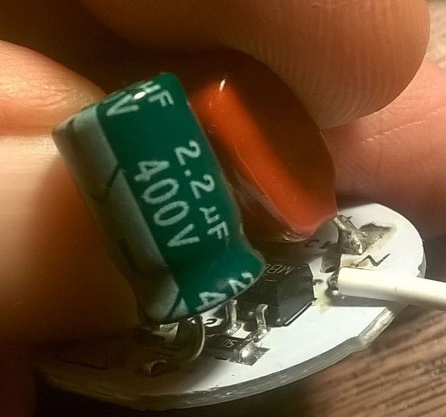
just shows the cap values and the other resistor.
since I was not trying to repair the light, the old driving circuit was not particularly important.
this was an e-bay special light, non-dimming, got 42 LED's for a couple bux.