Uno R4 schematic

I have got the Clock Frequency Accuracy Measurement Circuit (CAC) module working and measured the HOCO frequency using an external signal-generator running at 1 kHz as the reference (at 1000.0000 Hz on the display).

This external clock is attached to the "Heart" pad on the back of the board, so this pad does actually have a purpose!

I am getting consistently getting 47.999 MHz, hour after hour.

Even when I hit the chip with some freeze-spray, it doesn't budge.

I have to increment or decrement the sig-gen by 0.02Hz to get a shift to 48.000 or 47.998 as the timing for the CAC counter is changed.

I assume that this accuracy is good enough for the CAN bus specs???

Note: This is without fiddling with the HOCO User Trimming Control Register (HOCOUTCR) as that is prohibited when using the HOCO for the USB clock.

1 Like

Thank you for sharing, we are looking into it.

2 Likes

:+1:

Please also look into the other recent threads about DNP components not (properly/consistently) identified:

It looks like a general review of all schematics might be in order ...

1 Like

Okay, my R4 code is up on GitHub.

Plus code for a ATmega32u4 Leonardo for those who don't have access to a sig-gen.

https://github.com/TriodeGirl/Arduino__UNO_R4_CTC_Clock_Frequency_Accuracy_Measurement_Circuit

Note: the sig-gen may be more accurate in ultimate digits, but mine is pretty pants as far as cycle-to-cycle stability is concerned with over 100nS jitter!

On the other hand, the ATmega32u4 with it's 16.000MHz crystal and using Timer4 is more like 1nS cycle-to-cycle (yes, seriously).

2 Likes

I am an Arduino Leonardo user who needs a stable (not an accurate) processor clock to be able to rely on a repeatable delay. A repeatability of order 1ns is adequate and Leonardo fulfills the requirement while Uno doesn't because it doesn't use a proper quartz as a clock but a less stable ceramic oscillator.
My question is now if Arduino R4 would perform as the Leonardo or the Uno without having to test it, thanks p.-

Thank you very much, very useful reply. After looking at the board picture (the 4 tinned unused posts) I realize that there is plenty of room to add a crystal to the R4 Minima relatively easily which would allow to do so with a relatively bulkier temperature controlled xtal which would in turn improve the clock rate stability by a couple of order of magnitude. Do you have any reference to anybody who has added a regular xtal to the R4 Minima board? I am also interested in understanding how wide would be the choice of xtal frequency for the arduino board to work well.

It would be relatively easy to fit a proper xtal to the Minima, only two of the four pads connect so clean them up first with solder wick and then put in the appropriate surface mount part.
I used an old-style xtal because that is what I had to hand, and it needed a LOT more capacitance than I was expecting, hence the little forest of caps.

Code here should help with clock switching, etc:

https://github.com/TriodeGirl/Arduino-UNO-R4-Wake_from_interrupt-and-system-clock-switching

1 Like

Very useful thanks, since I would fit a relatively large temperature controlled Xtal your old style Xtal is actually much more realistic for me than a surface mount one.
I would love to understand more about the software side of the process though, I am confused by the relationship among the Xtal frequency vs the clock frequency and how one should let the firmware know of the change.
If anybody knows about it, it would be useful for me to see a description of the analogous process in the case of the swap of the a regular UNO ceramic oscillator with a xtal, which must have occurred more often

1 Like

Hi @pepic ,

I have put up some new clock code on GitHub which might help:

https://github.com/TriodeGirl/Arduino-UNO_R4_HOCO_to_External-Clock_on_EXTAL_pin_change

Shows updating the PLL, etc. :slight_smile:

5 Likes

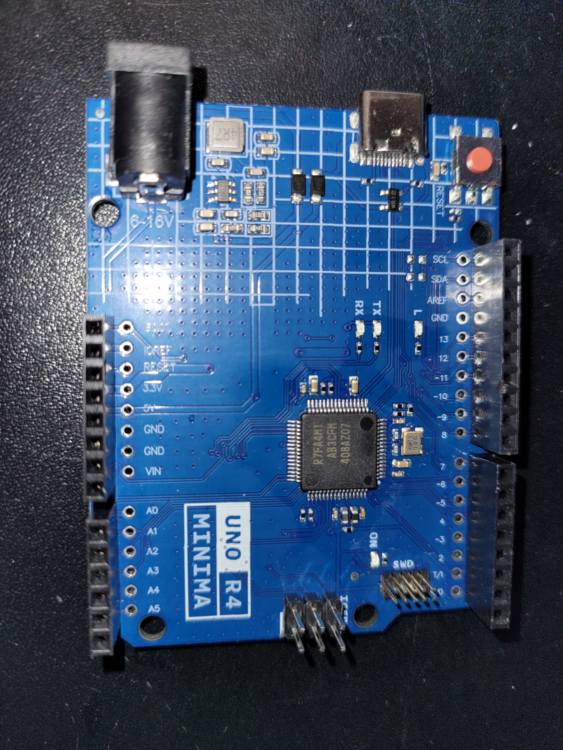
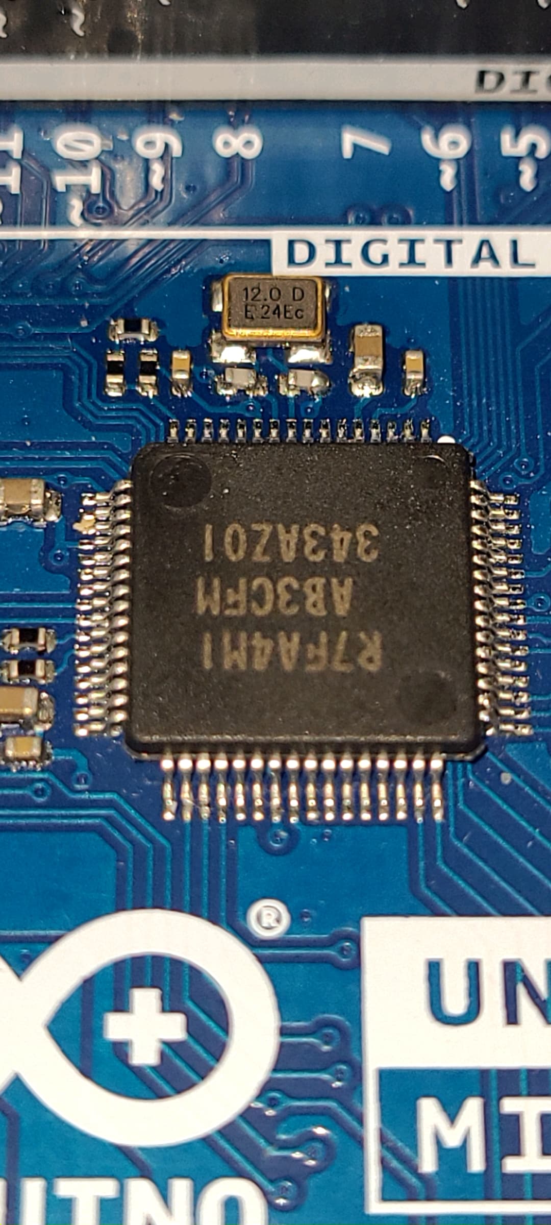
I wanted develop up a measurement system based on an Uno R4 Minima for some specific reasons (e. g. 24V supply, integrated DAC, footprint, resolution of micros() command etc.). While Susan Parker shows that the HOCO is very precise in the R4 Minima that she measured, the official spec says +/-1% within -20...+85C, which wouldn't be good enough for my purposes. I wanted to fit a crystal resonator to the board and use the MOSC as system clock input (at 48MHz). I found a R4 Minima clone with a 16MHz crystal already fitted (Arduino Uno R4 minima Clone - OTRONIC). Perfect for some trials, once again many thanks to Susan Parker for all the work and the insights you shared!!! Funfact: Reading out the clock registers of the R7FA4M1 on this clone (see Susan's post here: "Overclock" the R4 family - #3 by susan-parker) showed that it runs in HOCO mode and doesn't make any use of the crystal at all (they could leave it away ...). But having it on board, I tried the following:

Run with 16MHz input to MOSC, no PLL (i. e. ICK at 16MHz): works fine but of course at 1/3 of speed:

  *SYSTEM_PRCR = 0xA501;                        // enable writing to clock registers
  *SYSTEM_MOMCR = 0x0;                          // set oscillator mode to 10..20MHz and resonator
  *SYSTEM_MOSCCR = 0x0;                         // set main oscillator running
  while(*SYSTEM_MOSCCR != 0x0) {}               // wait until updated
  while(*SYSTEM_OSCSF & 0b00001000 == 0) {}     // wait until MOSC stable
  *SYSTEM_SCKSCR = 0x3;                         // select main clock
  *SYSTEM_PRCR = 0xA500;                        // disable writing to clock registers

Run with 16MHz input to MOSC, PLLMUL = 12; PLLDIV = 4 (i. e. ICK at 48MHz): works fine but violates spec (PLL input > 12.5MHz):

  *SYSTEM_PRCR = 0xA501;                        // enable writing to clock registers
  *SYSTEM_MOMCR = 0x0;                          // set oscillator mode to 10..20MHz and resonator
  *SYSTEM_MOSCCR = 0x0;                         // set main oscillator running
  while(*SYSTEM_MOSCCR != 0x0) {}               // wait until updated
  while(*SYSTEM_PLLCR != 0x1) {}                // confirm that PLL is stopped
  while(*SYSTEM_OSCSF >> 1 != 0b0000100) {}     // wait until MOSC stable and PLL stable off
  *SYSTEM_PLLCCR2 = 0b10001011;                 // set PLL *12 / 4
  delayMicroseconds(8);
  *SYSTEM_PLLCR = 0x0;                          // start PLL
  while(*SYSTEM_OSCSF >> 1 != 0b0010100) {}     // wait until MOSC stable and PLL stable 

  *SYSTEM_SCKSCR = 0b101;                       // select main clock PLL
  *SYSTEM_PRCR = 0xA500;                        // disable writing to clock registers

Run with 16MHz input to MOSC, PLLMUL = 6; PLLDIV = 2 (i. e. ICK at 48MHz): works fine but violates spec (PLL input > 12.5MHz and PLLMUL < 8):

  *SYSTEM_PLLCCR2 = 0b01000101;                 // set PLL *6 / 2

To stay within all specs I then substituted the 16MHz by a 12MHz crystal (I felt quite brave as it was my first real SMD soldering ever :slight_smile: ) and run with 12MHz input to MOSC, PLLMUL = 8; PLLDIV = 2 (i. e. ICK at 48MHz): works fine and doesn't violate any spec:

  *SYSTEM_PLLCCR2 = 0b01000111;                 // set PLL *8 / 2

dela(), millis() and micros() work as expected, accuracy I will try to check next.
Maybe this helps those who try to fiddle around with the clocks and crystals ...

2 Likes

I loaded R4 MINIMA bootloader inside a Weact Studio RA4M1 board wich has boot 16Mhz and 32.768Khz external crystal resonators and use Susan Parker code ...

1 Like

I note in the data-sheet:

Table 48.17 Operation frequency value in high-speed operating mode
Conditions: VCC = AVCC0 = 2.4 to 5.5 V

... the very wide operating voltage specifications.

Given that I have successfully run the System-Clock at 96MHz on the Minima with a VCC of 4.7 V it is likely that the PLL limit of 12MHz can be fudged at 16MHz when operating at a nominal 5V supply; but perhaps not reliably at 3.3 V over the full spec temperature range.

Operating at these out-of-spec frequencies for tests or non-life-critical home projects is fine, but I would not recommend it for anything that can cause damage or harm if it goes wrong.

It's a shame that the Watch-Dog timer function isn't available in the standard Arduino RA4M1 bootloaders. It has to be specifically setup and for that one would need to use the e2studio IDE.

Update: The a. m. clone only has 16V as max input voltage (I'd like to power directly with 24V of my environment), so I went the next step: I upgraded the original Arduino Uno R4 Minima with 2 SMD caps (18pF) and the 12MHz quartz (12,000000-MT: Keramik-SMD-Quarz 2,5x3,2x0,7mm 12,0 MHz bei reichelt elektronik). A bit challenging regarding SMD soldering of the caps, but it works. 18pF seems to be a reasonable capacity, the EXTAL signal looks fine.


I do not intend to fudge the system to higher clock rates but to an exact timing whilst staying within all processor specifications. In a first trial I compared the Arduino timing (EXTAL for MOSC) with my PC clock and end up with 290ms difference after approx. 3.5hrs, which is about 24ppm difference (whichever of the two is more accurate...). I have no calibrated time normal available, maybe I should look for a GPS time?

3 Likes

Nice! :slight_smile:

1 Like

Thanks! :blush:
By teh way: The manufacturer of the quartz recommends 12pF caps, which I hadn't available.

1 Like

18pF caps should just affect the tuning… and the exact capacitance also depends on the processor XTAL circuit characteristics - which will likely have some variations especially depending what VCC the processor is being run on!
The processor should now run with a much better stability. :slight_smile:

Be careful on 24V - it seems OK for the Arduino board on its own, but any additional load and it can overheat:
Power supply hot - UNO R4 / UNO R4 Minima - Arduino Forum

Brian

1 Like

@brig001
Thanks for the warning, I wasn't aware that this could be so sensitive. In my current setup I measure a maximum of 38mA when supplying 24V to VIN. The simple circuits that I supply via the 5V out pin of the Uno board draw max. 85mA, via the 3.3V output pin it is only about 3 ... 4 mA.
With my “calibrated fingertips” I can't feel any significant heating on the ISL854201. But since I still need to expand my circuits a bit, I'll keep an eye on that ...

Weird; it has a buck (switching) regulator, so you'd think it would do better.