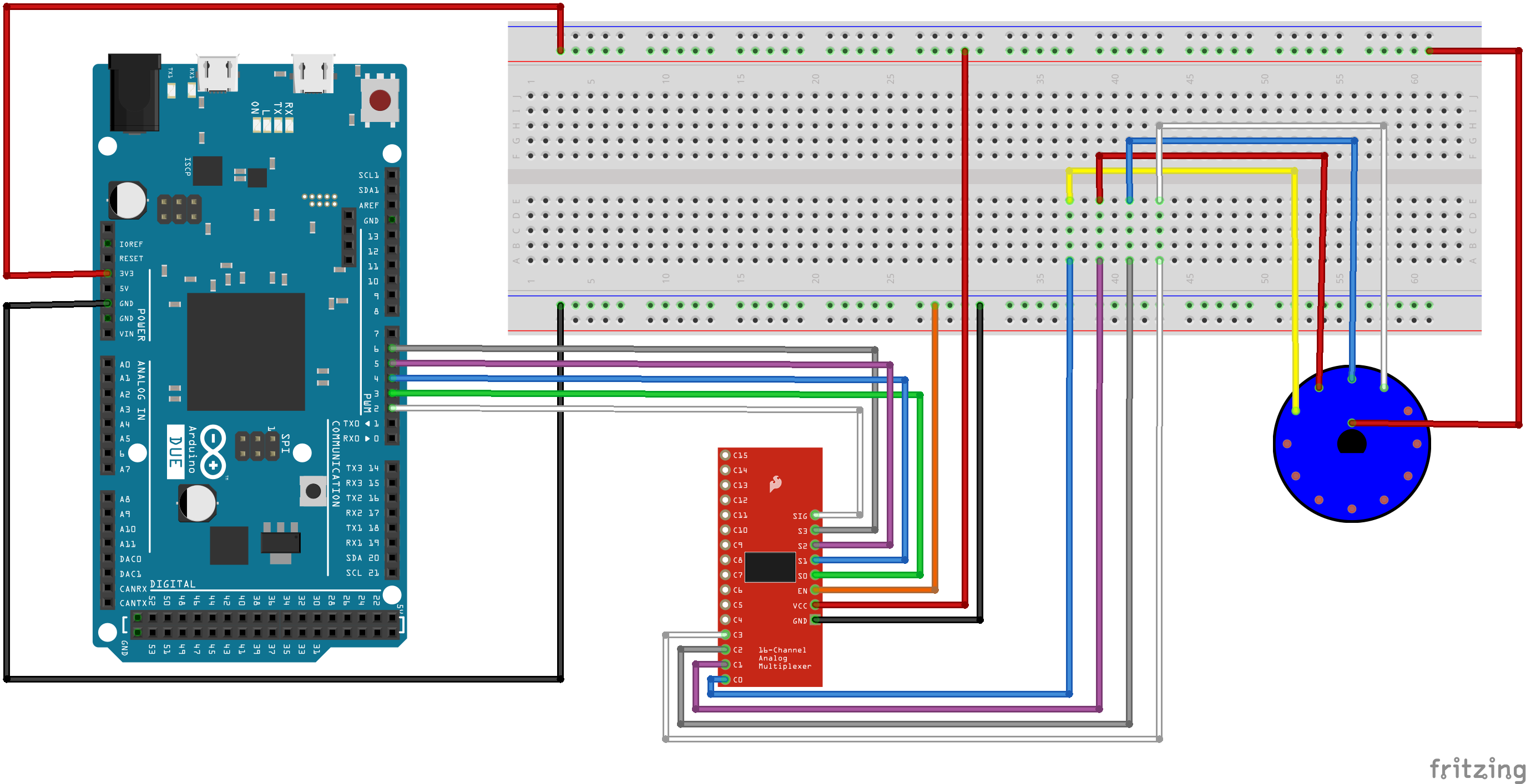
Hi there - I'm building a flight-sim button box that will need several rotary switches (not encoders) and other buttons and am trying to use the CD74HC4067 (no-name boards from Amazon UK at the moment) to reduce the input count on to the Due.
I have been using the often-quoted basic sketch (as reproduced here) to test the basics - but it is apparent that the inputs are erratic and cannot be trusted. So far I've tried two of the five 4067s I have to hand.
Searching this forum suggested possibly that all of the C0-15 inputs on the 4067 might need a grounding capacitor? Is that where I'm going wrong?
int s0 = 3;
int s1 = 4;
int s2 = 5;
int s3 = 6;

//Mux in "SIG" pin
int SIG_pin = 2;


void setup() {
  pinMode(s0, OUTPUT);
  pinMode(s1, OUTPUT);
  pinMode(s2, OUTPUT);
  pinMode(s3, OUTPUT);
  pinMode(SIG_pin, INPUT);

  digitalWrite(s0, LOW);
  digitalWrite(s1, LOW);
  digitalWrite(s2, LOW);
  digitalWrite(s3, LOW);

  Serial.begin(9600);
}


void loop() {

  //Loop through and read all 16 values
  for (int i = 0; i < 16; i++) {
    Serial.print("Value at channel ");
    Serial.print(i);
    Serial.print("is : ");
    Serial.println(readMux(i));
    delay(1000);
  }
}


int readMux(int channel) {
  int controlPin[] = { s0, s1, s2, s3 };

  int muxChannel[16][4] = {
    { 0, 0, 0, 0 },  //channel 0
    { 1, 0, 0, 0 },  //channel 1
    { 0, 1, 0, 0 },  //channel 2
    { 1, 1, 0, 0 },  //channel 3
    { 0, 0, 1, 0 },  //channel 4
    { 1, 0, 1, 0 },  //channel 5
    { 0, 1, 1, 0 },  //channel 6
    { 1, 1, 1, 0 },  //channel 7
    { 0, 0, 0, 1 },  //channel 8
    { 1, 0, 0, 1 },  //channel 9
    { 0, 1, 0, 1 },  //channel 10
    { 1, 1, 0, 1 },  //channel 11
    { 0, 0, 1, 1 },  //channel 12
    { 1, 0, 1, 1 },  //channel 13
    { 0, 1, 1, 1 },  //channel 14
    { 1, 1, 1, 1 }   //channel 15
  };

  //loop through the 4 sig
  for (int i = 0; i < 4; i++) {
    digitalWrite(controlPin[i], muxChannel[channel][i]);
  }

  //read the value at the SIG pin
  int val = digitalRead(SIG_pin);

  //return the value
  return val;
}
TIA!
